Living tissue ligation device

Active Publication Date: 2005-06-30
OLYMPUS CORP
View PDF8 Cites 273 Cited by
  • Summary
  • Abstract
  • Description
  • Claims
  • Application Information

AI Technical Summary

Benefits of technology

[0015] It is an object of the present invention to provide a living tissue ligation device by which an improvement in the gripped state of living tissue can

Problems solved by technology

However, this structure is designed to rotate the operating wire, and hence a large torque cannot be obtained, and the structure becomes complicated.
This makes it impossible to engage the arrowhead hook wit

Method used


Image

  • Living tissue ligation device
  • Living tissue ligation device
  • Living tissue ligation device

Examples


Example

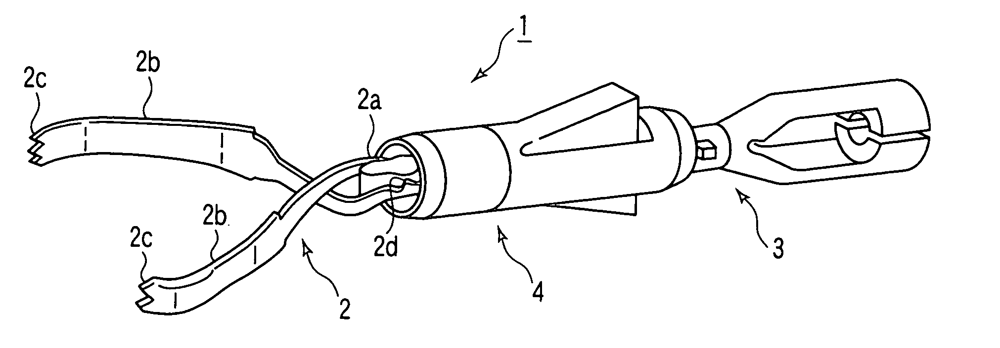
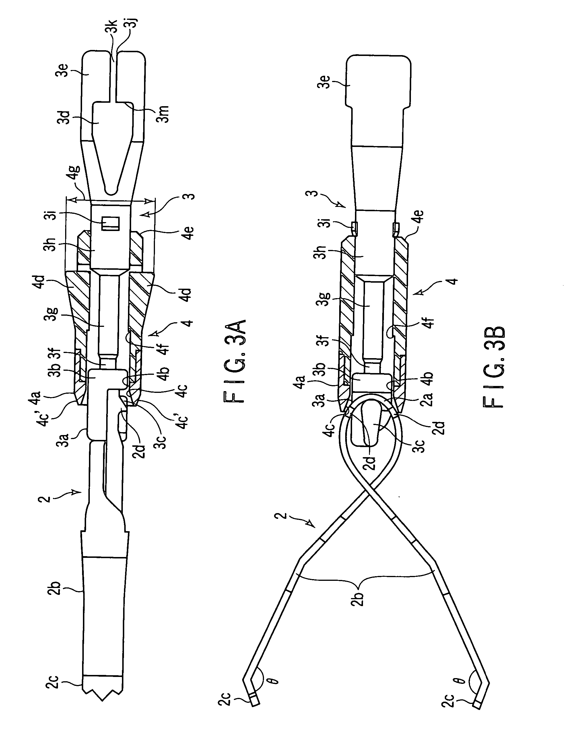
[0113] FIGS. 1 to 23 are associated with the first embodiment. FIG. 1 is a perspective view of a clip unit 1 of a living tissue ligation device. The clip unit 1 is comprised of a clip 2, a coupling member 3, and a press tube 4 serving as a fastening member.

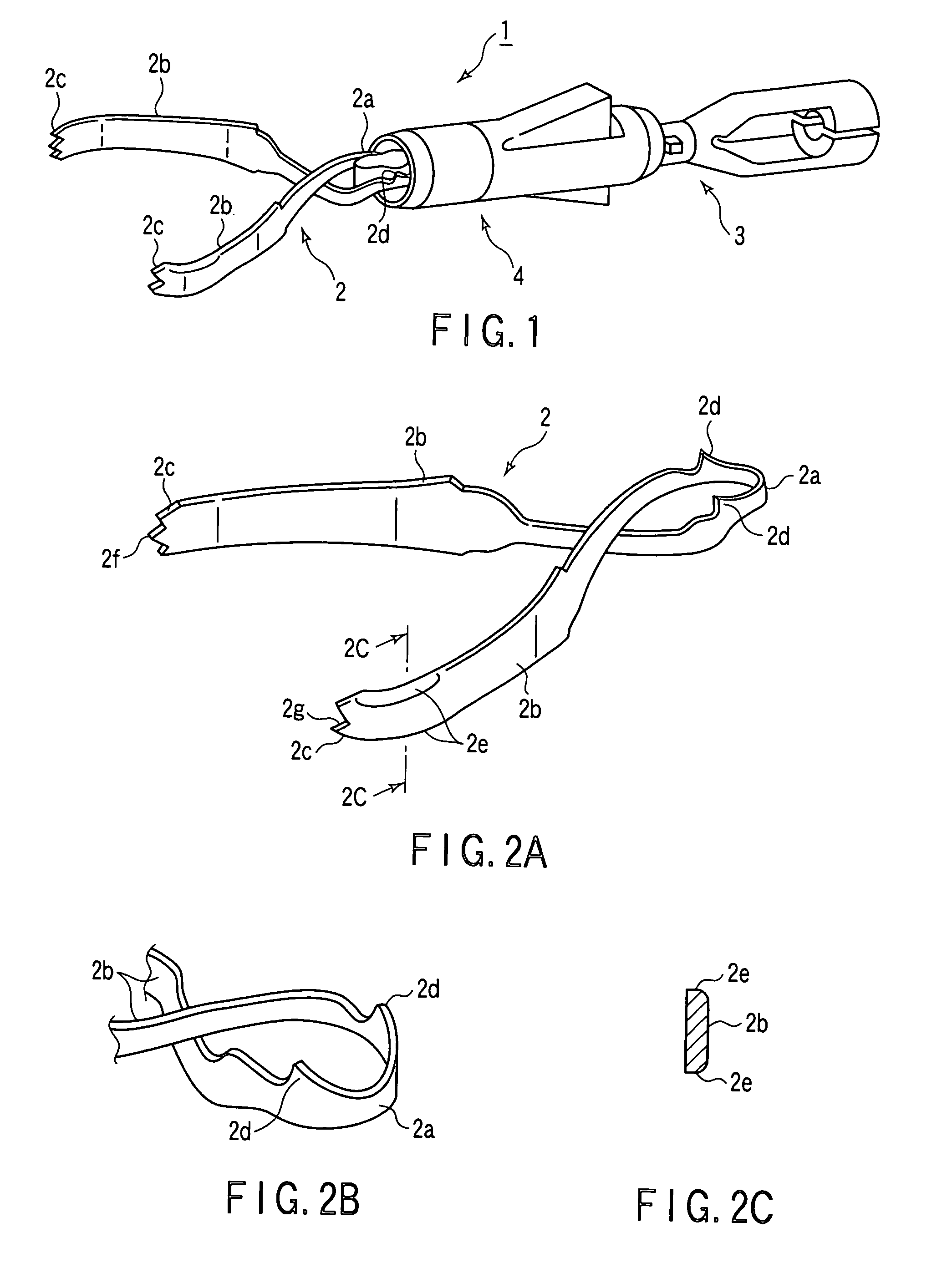
[0114] As shown in FIGS. 2A to 2C, the clip 2 is formed such that after a loop portion 2a is formed by bending a metal plate member such as a leaf spring member made of stainless steel or the like at its middle portion, a pair of arms 2b having a property of spreading apart are made to intersect at a position near the loop portion 2a and extend with their distal end portions being spaced apart from each other. Tissue gripping portions 2c are formed on the distal end portions of the arms so as to face each other.

[0115] That portion of the metal plate member which corresponds to the intersecting portion of the arms 2b of the clip 2 is formed to have a width smaller than that of the distal end portions, thereby preventing the inter...

Example

[0178] FIGS. 24 to 26C show the second embodiment, and show a peel pack 50 which houses a sterilized clip case 30. As shown in FIG. 24, the peel pack 50 is a combination of a high-density polyethylene mount with a polyethylene coating and a polyethylene and PET multilayer film and has a rectangular, bag-like shape. The peel pack 50 has triangular notched portions 51. As shown in FIG. 25, therefore, an operator can form an opening portion 52 by tearing the peel pack 50 from the notched portion 51 with his / her fingers.

[0179] After the peel pack 50 housing the clip case 30 is provided with the opening portion 52, a clip unit 1 is attached to a ligation device in the following manner. First of all, as shown in FIG. 26A, the distal end portion of an introduction tube 5 is inserted from the opening portion 52 of the peel pack 50 in the direction indicated by the arrow. As shown in FIG. 26B, the introduction tube 5 is inserted into an introduction tube insertion portion 40 from an introdu...

Example

[0180]FIGS. 27A to 34 show the third embodiment. The same reference numerals as in the first embodiment denote the same constituent parts in the third embodiment, and a description thereof will be omitted. According to Jpn. Pat. Appln. KOKAI Publication No. 8-280701 described in the prior art, the click is pulled into the clamping ring by using the operating wire, and the living tissue is ligated by closing the arms of the clip. The clamping ring is structured such that the coupling member is inserted in the cylindrical tube-like member having the two open ends. The loop portion of the clip is engaged with the distal end portion of the coupling member, and the coupling member is pulled to the operator side to house the clip in the clamping ring in the closed state.

[0181] The coupling member may therefore move in the axial direction of the clamping ring inside the clip case or introduction tube to disengage from the clip. As a result, the clip may separate from the coupling member. ...


PUM


Abstract

This invention includes a clip having arms which grip living tissue, a press tube serving as a clamping member which is fitted and mounted on the clip to close the arms of the clip, a coupling member which can be inserted into the press tube and engages with the clip, and projections serving as lock portions which hold the arms of the clip in a closed state when the clip engages with the press tube.

Description

CROSS-REFERENCE TO RELATED APPLICATIONS [0001] This is a Continuation Application of PCT Application No. PCT / JP03 / 10598, filed Aug. 21, 2003, which was not published under PCT Article 21(2) in English. [0002] This application is based upon and claims the benefit of priority from prior Japanese Patent Applications No. 2002-240673, filed Aug. 21, 2002; No. 2002-288934, filed Oct. 1, 2002; and No. 2002-288935, filed Oct. 1, 2002, the entire contents of all of which are incorporated herein by reference.BACKGROUND OF THE INVENTION [0003] 1. Field of the Invention [0004] The present invention relates to a living tissue ligation device which is endoscopically inserted into a body cavity and ligates living tissue with a clip. [0005] 2. Description of the Related Art [0006] As a living tissue ligation device, for example, Jpn. Pat. Appln. KOKAI Publication No. 8-280701 has been known. As a polypectomy snare device, WO 01 / 10321A1 has been known. Jpn. Pat. Appln. KOKAI Publication No. 8-280701...

Claims


Application Information

Patent Timeline
IPC IPC(8): A61B17/08
CPCA61B17/1222A61B17/1227A61B17/1285Y10T24/44701A61B2017/2905A61B2017/2931A61B2019/0267A61B19/026A61B2050/314A61B50/30A61B2017/0053
Inventor KIMURA, KOMATSUNO, KIYOTAKASUZUKI, TAKAYUKIMURAMATSU, JUNICHIKOBAYASHI, TSUKASASHIMONAKA, HIDEKI
Owner OLYMPUS CORP
Why Eureka
Try Eureka