
Electrical stimulation system and associated apparatus for securing an electrical stimulation lead in position in a person's brain

a technology of electrical stimulation and electrical stimulation leads, which is applied in the field of electric stimulation systems, can solve the problems of difficult, if not impossible, to achieve in practice, and the electrical stimulation leads may be particularly prone to being dislodged, so as to simplify the lead implantation procedure, reduce the risk of injury, and simple and easy insertion

Inactive Publication Date: 2005-06-30
ADVANCED NEUROMODULATION SYST INC
View PDF11 Cites 111 Cited by
  • Summary
  • Abstract
  • Description
  • Claims
  • Application Information

AI Technical Summary

Benefits of technology

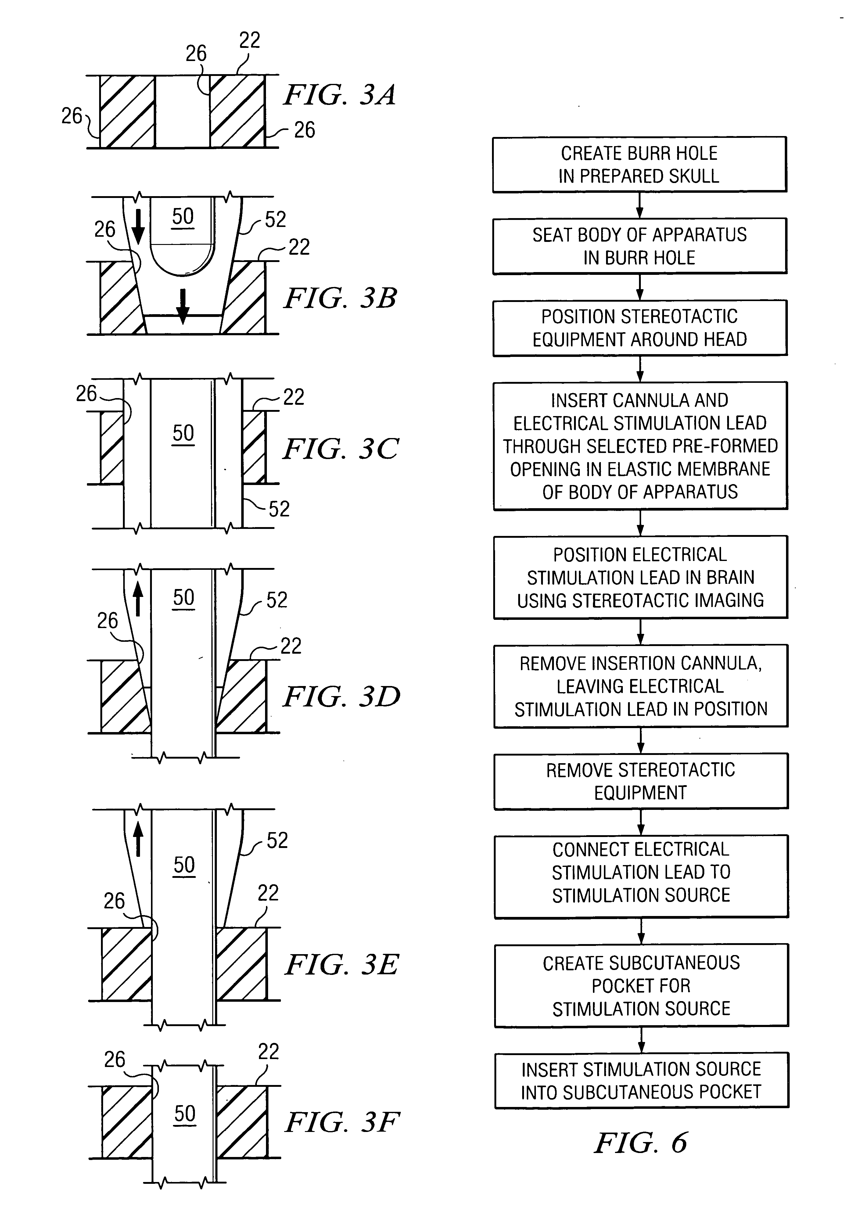
[0010] Certain embodiments of the present invention may provide one or more technical advantages. In contrast to previous burr hole covers, the apparatus of the present invention provides an elastic membrane including one or more pre-formed openings that penetrate the entire thickness of the membrane and through which CSF may freely pass. In this embodiment, openings are formed in membrane solely for purposes of securing the electrical stimulation lead in position in the brain after implantation, without regard to CSF leakage. Significantly, the electrical stimulation lead may be simply and easily inserted through a selected pre-formed opening and secured in position as the membrane elastically contracts on the lead in the selected pre-formed opening. The electrical stimulation lead need not be physically forced through the membrane to form a puncture hole for securing the lead as with previous burr hole covers, which may reduce the risk of injury to the patient or damage to the lead or other medical equipment, may simplify the lead implantation procedure, and may provide one or more other benefits. One or more other technical advantages may be readily apparent to one skilled in the art from the figures, descriptions, and claims included herein.

Problems solved by technology

An electrical stimulation lead may be particularly prone to being dislodged when a stereotactic frame is disassembled and removed from the head, for example, after insertion of the lead.
This is difficult, if not impossible, to accomplish in practice.

Method used


Image

  • Electrical stimulation system and associated apparatus for securing an electrical stimulation lead in position in a person's brain
  • Electrical stimulation system and associated apparatus for securing an electrical stimulation lead in position in a person's brain
  • Electrical stimulation system and associated apparatus for securing an electrical stimulation lead in position in a person's brain

Examples


Embodiment Construction

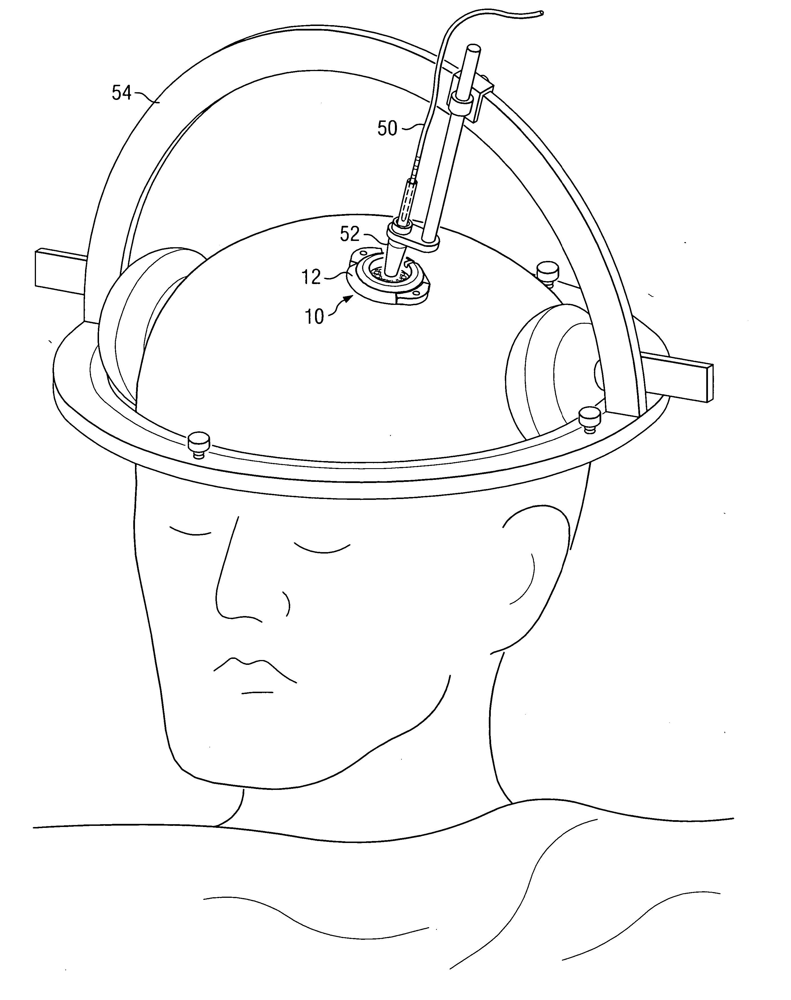
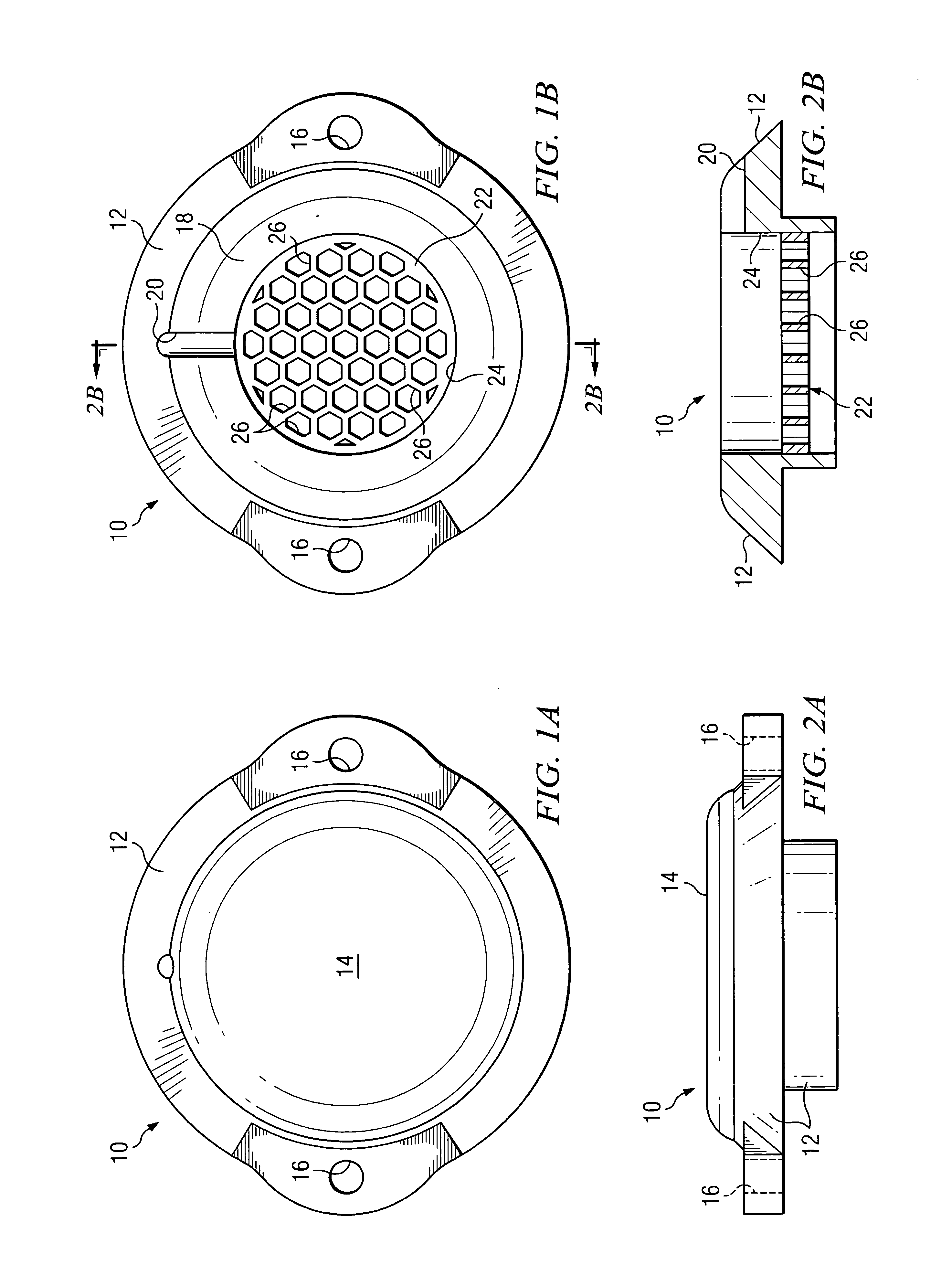
[0021]FIGS. 1A-2B illustrate an example apparatus 10 for securing an electrical stimulation lead in position in a person's brain, the lead implanted in the person's brain through a burr hole formed in the person's skull. For example, the burr hole may be formed to provide access to the brain for implantation of the electrical stimulation lead for deep brain or other brain stimulation, and apparatus 10 may be used to secure the lead during and after precise positioning of the lead in the brain using a stereotactic or other surgical procedure. The electrical stimulation lead may be a percutaneous lead having one or more circumferential electrodes that emit electrical energy substantially radially in all directions, a laminotomy or “paddle style” lead having one or more directional electrodes that emit electrical energy in a direction substantially perpendicular to a surface of the lead, or any other suitable lead. As described more fully below, the electrodes of the electrical stimula...


PUM


Abstract

In one aspect, an apparatus is provided for securing an electrical stimulation lead in position in a person's brain. The apparatus includes a body configured to seat within a burr hole formed in the person's skull. The apparatus also includes a central elastic membrane coupled to the body and extending across a central aperture of the body. The elastic membrane includes a number of pre-formed openings provided for purposes of securing the lead in position within the brain after implantation. Each pre-formed opening may penetrate through an entire thickness of the elastic membrane. Each pre-formed opening may be selected for insertion of the lead into the brain. Each pre-formed opening is adapted to elastically expand as the lead is inserted through the pre-formed opening and positioned in the brain and is adapted to elastically contract on the lead to secure the lead in position within the brain after implantation.

Description

RELATED APPLICATIONS [0001] This application claims the benefit under 35 U.S.C. § 119(e) of U.S. Provisional Application Ser. No. 60 / 528,604, filed Dec. 11, 2003.TECHNICAL FIELD OF THE INVENTION [0002] This invention relates generally to electrical stimulation systems designed for implantation into a person's body and more particularly to an electrical stimulation system and associated apparatus for securing an electrical stimulation lead in position in a person's brain. BACKGROUND [0003] Electrical energy is applied to the brain to treat a variety of clinical conditions such as movement disorders or chronic pain. One method of delivering electrical energy to the brain involves inserting an electrical stimulation lead through a burr hole formed in the skull and then positioning the lead in a precise location adjacent a target area of the brain to be stimulated such that stimulation of the target area causes a desired clinical effect. For example, one desired clinical effect may be c...

Claims


Application Information

Patent Timeline
Patent Type & Authority Applications(United States)
IPC IPC(8): A61B5/03A61B19/00A61N1/05
CPCA61B5/031A61B5/6864A61N1/0539A61N1/0529A61B19/201A61B90/11
Inventor BLACK, DAMON R.DAGLOW, TERRY D.JONES, ROBERT E.
Owner ADVANCED NEUROMODULATION SYST INC
Learn More