Configuration management apparatus and method

a technology of configuration management and management apparatus, applied in the direction of memory address/allocation/relocation, input/output to record carriers, instruments, etc., can solve the problems of shortening the resource assigned to another storage device, large consumption of virtualization device cache,

Inactive Publication Date: 2005-06-30
HITACHI LTD
View PDF11 Cites 26 Cited by
  • Summary
  • Abstract
  • Description
  • Claims
  • Application Information

AI Technical Summary

Benefits of technology

[0005] The technology described in Patent Document 1 relates to data migration from the old storage device to the new storage device, and does not consider to take over a configuration in the old storage device, to the new storage device. Usually, in the old storage device, a configuration used for volume access performance improvement such as cache allocation...

Problems solved by technology

On one hand, when the virtualization device takes over a configuration of the old storage-device, a resource such as cache of the virtualization device is c...

Method used


Image

  • Configuration management apparatus and method
  • Configuration management apparatus and method
  • Configuration management apparatus and method

Examples


first embodiment

[0053] A computer system of a first embodiment of the present invention will be described by way of taking such a case, as an example, that a storage area network between a host and a storage device is built up on a Fibre Channel network.

[0054] (1) System Configuration

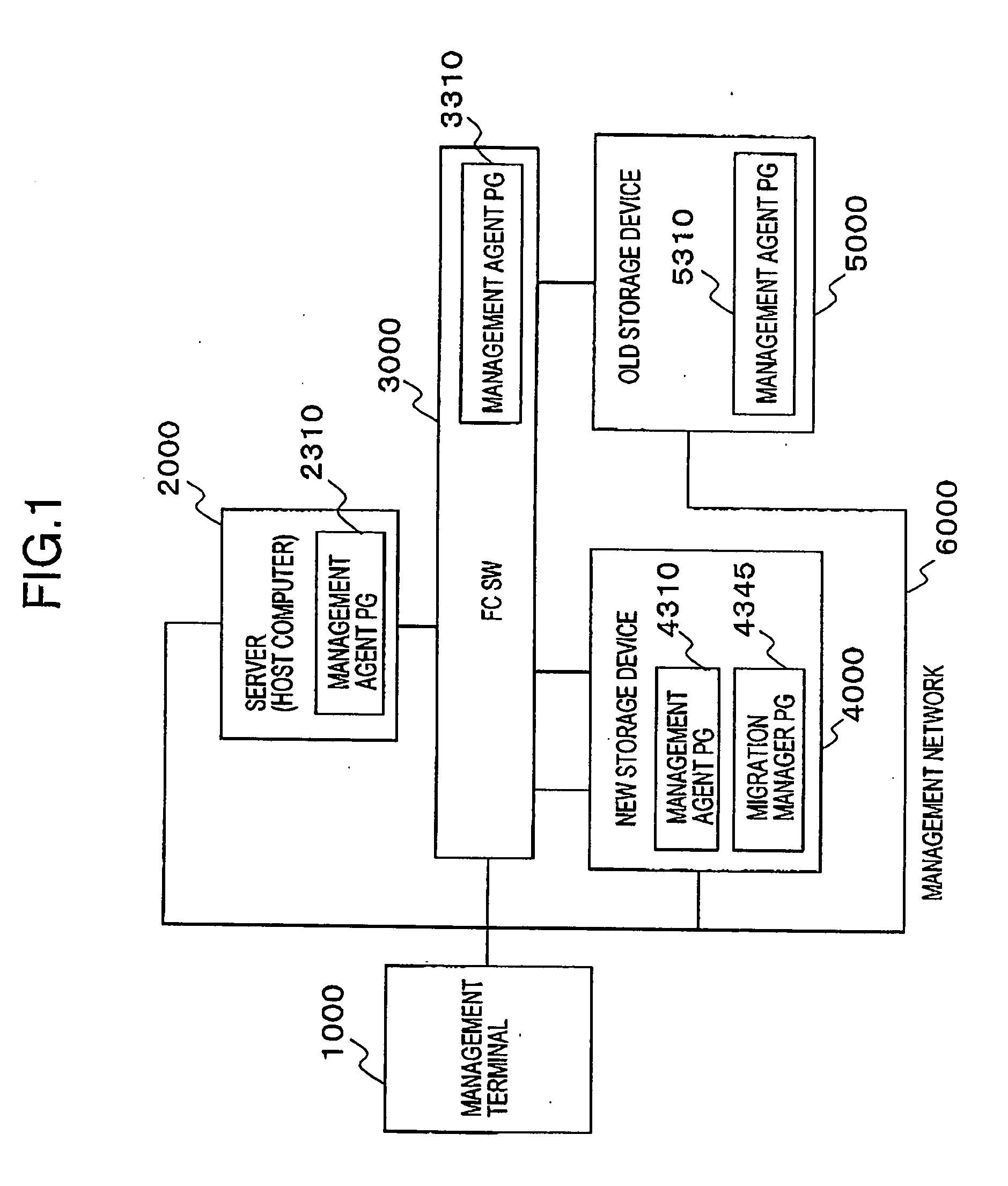
[0055]FIG. 1 is a schematic diagram of the computer system to which the first embodiment of the present invention is applied.

[0056] As shown in the figure, the computer system of this embodiment is configured such that a management terminal 1000, a Fibre Channel switch (FC SW) 3000 which configures a storage area network, an existing old storage device 5000, a new storage device 4000 to be newly implemented, and a server 2000 which is a host computer are mutually connected by a management network 6000 such as Ethernet (trademark) and so on.

[0057] The server 2000, the FC SW 3000, the new storage device 4000, and the old storage device 5000 have, management agent PG (program) 2310, 3310, 4310, 5310, respectively. The...

second embodiment

[0143] Next, a second embodiment of the present invention will be described.

[0144]FIG. 21 is a schematic diagram of a computer system to which the second embodiment of the present invention is applied. As shown in the figure, different points between the computer system of this embodiment and the computer system of the first embodiment shown in FIG. 1 are as follows: a plurality of old storage devices 5000 which become migration sources of logical volumes and new storage devices 4000 which become migration destinations are provided respectively. As a device in which the migration manager PG 4345 is installed, there is a management server 8000 which is a different device from the new storage device 4000 is provided; and the management server 8000 is connected to the management network 6000. Others are the same as in the computer system of the first embodiment. In addition, in this embodiment, the same reference numerals and signs are given to ones having the same functions as in the...

third embodiment

[0149] Next, a third embodiment of the present invention will be described.

[0150] (1) System Configuration

[0151]FIG. 23 is a schematic diagram of a computer system to which the third embodiment of the present invention is applied. As shown in the figure, a different point between the computer system of this embodiment and the computer system of the first embodiment shown in FIG. 1 is as follows; a new storage device which becomes a migration destination is a virtualization device 9000. Others are the same as in the computer system of the first embodiment. In addition, in this embodiment, the same reference numerals and signs are given to ones having the same functions as in the first embodiment.

[0152] The virtualization device 9000 manages a logical volume of the old storage device 5000, allocated to the server 2000, by a virtual volume, by using the following two functions. Function 1: Function which manages a storage area of the old storage device 5000 connected to the virtuali...


PUM


Abstract

To migrate a configuration that an old storage device has to a new storage devics.
A new storage device 4000 obtains a configuration of an old storage device 5000, by using a migration manager PG 4345, and prepares a logical volume definition of the new storage device 4000 on the basis of a logical volume definition which is included in the configuration. Also, on the basis of a cache allocation definition included in the configuration of the old storage device 5000 and cache capacity of the new storage device 4000, a cache allocation definition of the new storage device 4000 is prepared. Also, on the basis of a port bandwidth allocation definition included in the configuration of the old storage device 5000 and bandwidth capacity of a port of the new storage device 4000, a port bandwidth allocation definition of the new storage device 4000 is prepared. And, the logical volume definition, the cache allocation definition and the port bandwidth allocation definition which were prepared as above are set up in a configuration of the new storage device 4000.

Description

BACKGROUND OF THE INVENTION [0001] The present invention relates to a technology which manages a configuration such as cache allocation, port bandwidth management and so on in a storage device. [0002] As a mode which implements a new storage device in a computer system which has a server (host) and a storage device, there are an implementation mode which migrates all data in an old storage device to the new storage device and removes the old storage device, and an implementation mode which adds the new storage device with leaving over the old storage device and consolidates a storage area of the old storage device with the new storage device by a virtual volume. [0003] As the former implementation mode, there is a data migration technology described in WO97 / 09676 (hereinafter, referred to as Patent Document 1). In this technology, a new storage device and an old storage device are connected, and a data migration process is carried out during operation of a system, and thereby, down ...

Claims


Application Information

Patent Timeline
IPC IPC(8): G06F12/08G06F3/06G06F12/00
CPCG06F3/0605G06F12/0866G06F3/067G06F3/0647
Inventor YAMAMOTO, MASAYUKIKANEDA, YASUNORIMIMATSU, YASUYUKI
Owner HITACHI LTD
Why Eureka
Try Eureka