Exposure apparatus, maintenance method therefor, semiconductor device manufacturing method using the apparatus, and semiconductor manufacturing factory

a technology of exposure apparatus and maintenance method, which is applied in the direction of photomechanical apparatus, printers, instruments, etc., can solve the problems of difficult movement of the stage, insufficient purification of oxygen or moisture, and the inability to apply fluorine excimer lasers in low-oxygen-concentration environments, etc., and achieve the effect of purging

Inactive Publication Date: 2005-07-07
CANON KK
View PDF11 Cites 10 Cited by
  • Summary
  • Abstract
  • Description
  • Claims
  • Application Information

AI Technical Summary

Benefits of technology

[0022] In the preferred embodiment, the shield is so arranged as to prevent an opening of the reticle surface plate from deviating from a region defined by the shield.

Problems solved by technology

Thus, the fluorine excimer laser can only be applied in a low-oxygen-concentration environment.
For example, Japanese Patent Laid-Open No. 6-260385 discloses a method of spraying inert gas to a photosensitive substrate, which is not enough to purge oxygen or moisture.
However, the stage is difficult to move, and this method is not practical.
However, oxygen or moisture cannot be sufficiently purged because the space from a reticle holder for holding a reticle to a reticle surface plate for supporting a reticle stage is not surrounded.
In addition, a sheet glass is set on the reticle stage side serving as a movable portion, which increases the weight of the reticle stage.
In this case, the optical characteristics must be uniform within the scan stroke range, resulting in a very complicated process.
Scan operation while the tube is connected degrades the control characteristics of the reticle stage.

Method used


Image

  • Exposure apparatus, maintenance method therefor, semiconductor device manufacturing method using the apparatus, and semiconductor manufacturing factory
  • Exposure apparatus, maintenance method therefor, semiconductor device manufacturing method using the apparatus, and semiconductor manufacturing factory
  • Exposure apparatus, maintenance method therefor, semiconductor device manufacturing method using the apparatus, and semiconductor manufacturing factory

Examples


first embodiment

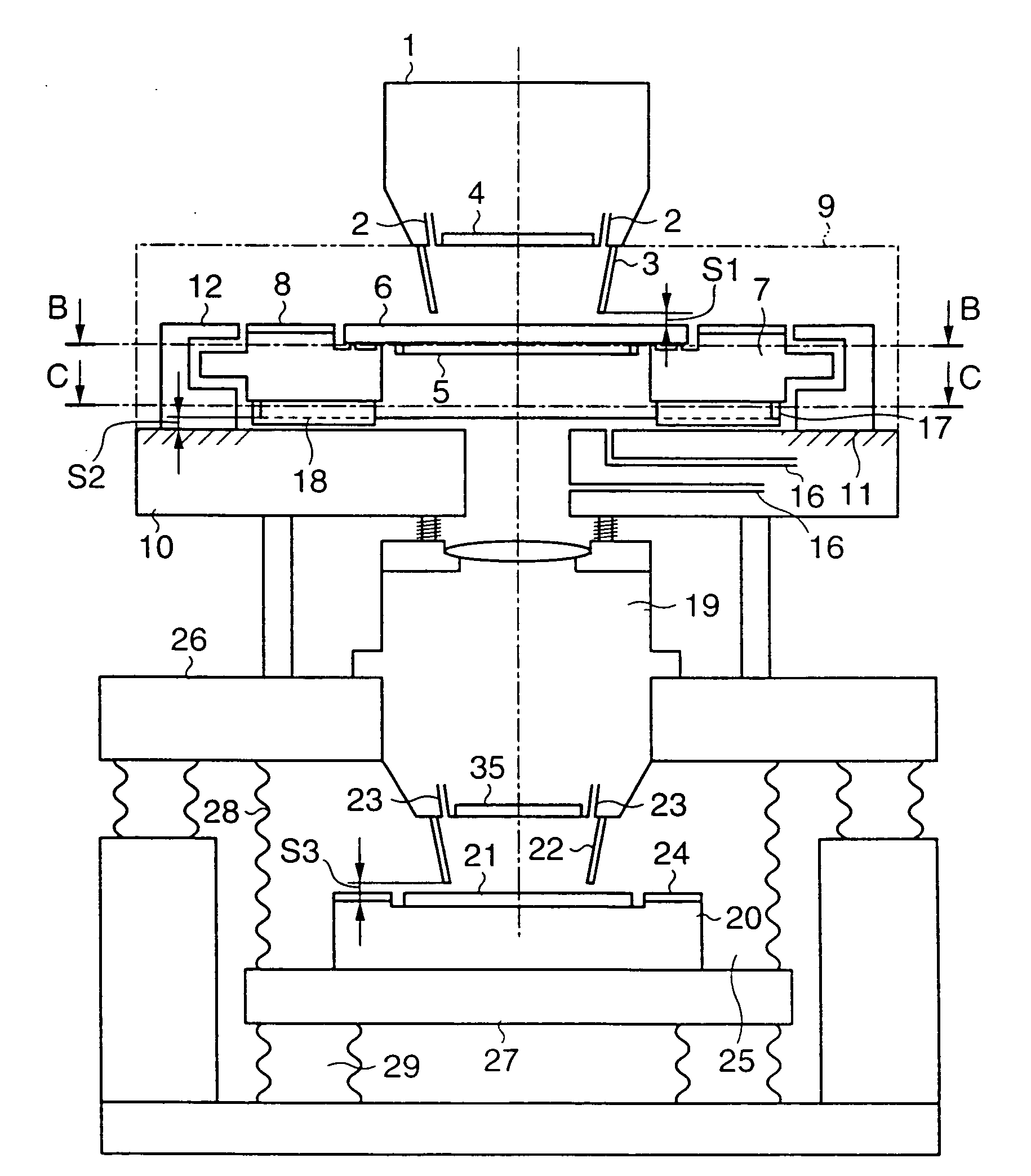
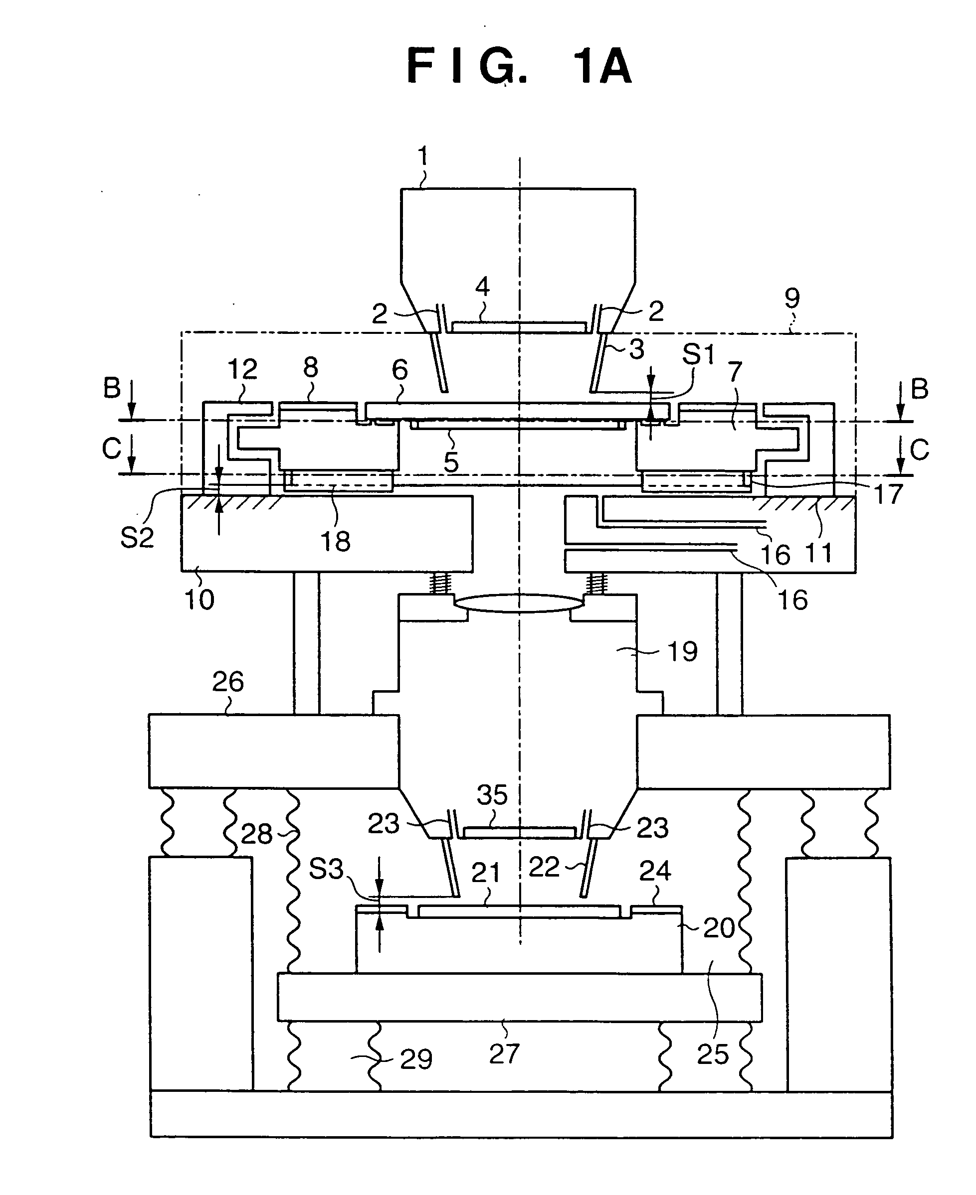
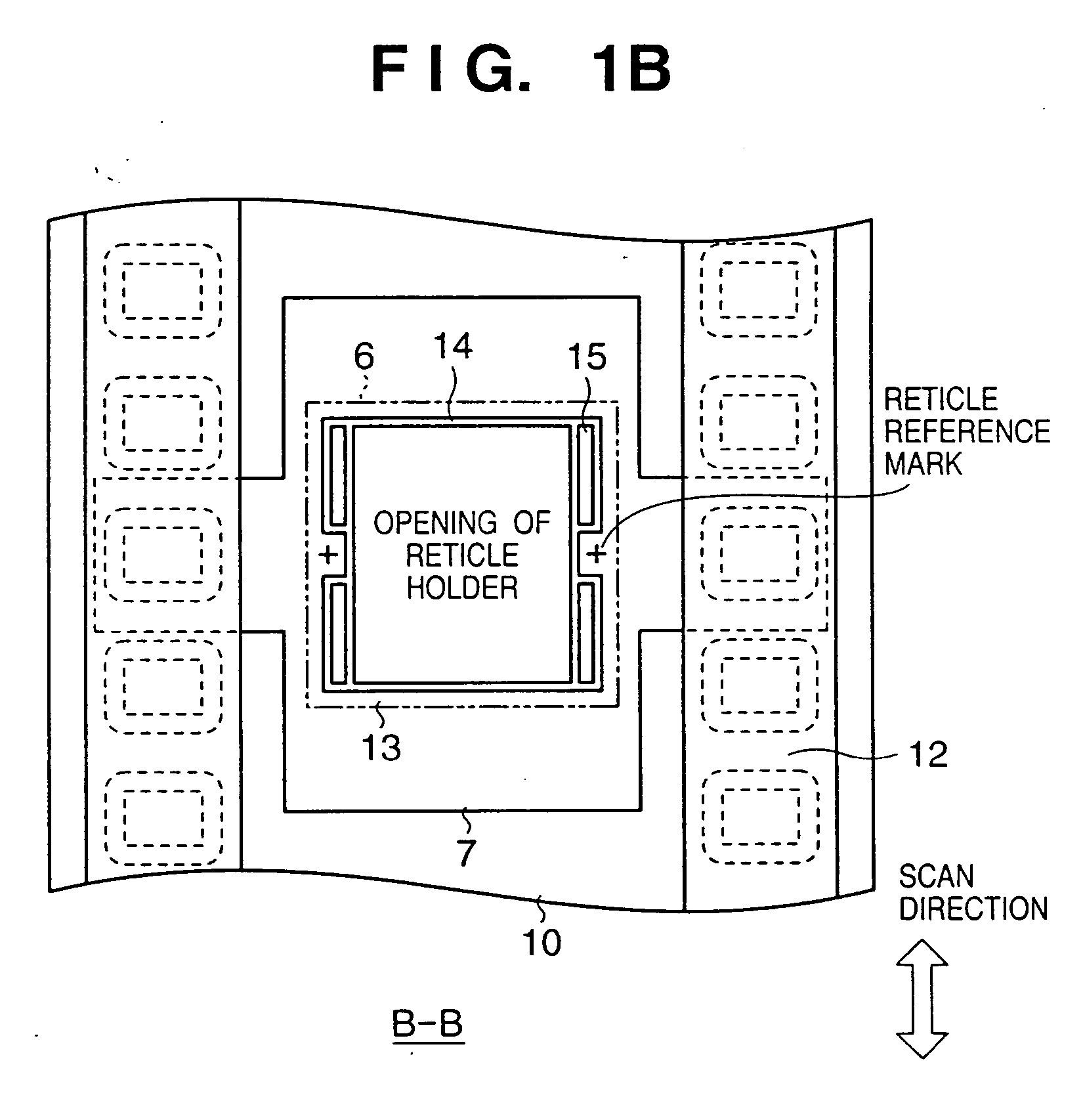
[0058]FIG. 1A shows the main part of a step & scan type projection exposure apparatus according to the first embodiment of the present invention. FIGS. 1B and 1C are sectional views of the exposure apparatus in FIG. 1A taken along the lines B-B and C-C, respectively. In FIGS. 1A to 1C, ultraviolet rays which have reached an illumination optical system 1 in the exposure apparatus from an ultraviolet source (not shown) irradiate a reticle 6 held by a reticle holder 13 on a reticle stage 7. A cover 3 serving as an enclosure for surrounding the ultraviolet path and shielding it from the surroundings extends from the reticle-side lower end of the illumination optical system 1 toward the vicinity of the reticle stage 7. Supply portions (including, e.g., a flow path and nozzle) 2 for supplying purge gas made of inert gas into the cover 3 are formed. The gap between the lower end of the cover 3 and the reticle 6 is S1. Inert gas such as nitrogen, helium, or argon is supplied from the illumi...

second embodiment

[0069]FIG. 2A shows the main part of a step & scan type projection exposure apparatus according to the second embodiment of the present invention. FIGS. 2B and 2C are sectional views of the exposure apparatus in FIG. 2A taken along the lines B-B and C-C, respectively. In the second embodiment, a sheet glass 30 is attached to the opening of a reticle surface plate 10 in place of the enclosure 17 described in the first embodiment. A first space 100 is defined by a reticle 6, a reticle stage 7, the reticle surface plate 10, and the sheet glass 30. A second space 200 is defined by the reticle surface plate 10, the sheet glass 30, and a projection optical system 19. The sheet glass 30 is laid out such that its upper surface (i.e., the surface on the reticle stage 7 side) is flush with the upper surface (i.e., the surface on the reticle stage 7 side) of the reticle surface plate 10. By reducing the step in this manner, the optical path extending from the lower surface of the reticle stage...

third embodiment

[0071]FIG. 3A shows the main part of a step & scan type projection exposure apparatus according to the third embodiment of the present invention. FIGS. 3B and 3C are sectional views of the exposure apparatus in FIG. 3A taken along the lines B-B and C-C, respectively. The third embodiment adopts both an enclosure 17 as in the first embodiment and a sheet glass 30 as in the second embodiment. A reticle surface plate 10 has gas supply portions 16 for supplying purge gas made of inert gas into a space 110 defined by a reticle 6, a reticle stage 7, a reticle surface plate 10, the enclosure 17, and the sheet glass 30, and a space 210 defined by the reticle surface plate 10, the sheet glass 30, and a projection optical system 19. The remaining arrangement is the same as that in the first embodiment.

[0072] In the exposure apparatus of the third embodiment, the purge area between the reticle 6 and the projection optical system 19 is divided. As a result, the concentration distribution of th...


PUM

PropertyMeasurementUnit
oscillation wavelengthaaaaaaaaaa

Abstract

Openings for transmitting ultraviolet rays are formed in a reticle stage (7) and a reticle surface plate (10) for supporting the reticle stage. A chuck groove (15) is formed in a reticle chuck surface (14) of a reticle holder (13). An opening for transmitting ultraviolet rays is also formed in the holder (13). An enclosure (17) for surrounding the ultraviolet path from the lower end of the stage (7) toward the vicinity of the reticle surface plate (10) is attached to the opening of the reticle stage (7). A supply port (16) for supplying purge gas made of inert gas into a space defined by a reticle (6), the stage (7), the enclosure (17), the surface plate (10), and a projection optical system (19) is formed.

Description

FIELD OF THE INVENTION [0001] The present invention relates to an exposure apparatus for projecting a mask pattern onto a photosensitive substrate via a projection optical system, a maintenance method for the apparatus, a semiconductor device manufacturing method using the apparatus, and a semiconductor manufacturing factory. BACKGROUND OF THE INVENTION [0002] A conventional manufacturing process for a semiconductor element such as an LSI or VLSI formed from a micropattern uses a reduction type projection exposure apparatus for transferring by reduction projection a circuit pattern drawn on a mask such as a reticle onto a substrate coated with a photosensitive agent. With an increase in the packaging density of semiconductor elements, demands have arisen for further micropatterning. Exposure apparatuses are coping with micropatterning along with the development of a resist process. [0003] Methods of increasing the resolving power of the exposure apparatus include a method of changin...

Claims


Application Information

Patent Timeline
Patent Type & Authority Applications(United States)
IPC IPC(8): G03F7/20G03F7/22H01L21/027
CPCG03F7/70525G03F7/70975G03F7/70933G03F7/70716H01L21/027
Inventor ARAKAWA, KIYOSHI
Owner CANON KK
Why Eureka
Try Eureka