System and method for improved retroactive recording and/or replay

a retroactive recording and retroactive technology, applied in the field of retroactive recoding or replay, can solve the problems of synchronizing the circular buffer with the cassette, and achieve the effects of less distortion, wider angles, and removal of distortions

Inactive Publication Date: 2005-07-07
MAYER YARON
View PDF22 Cites 40 Cited by
  • Summary
  • Abstract
  • Description
  • Claims
  • Application Information

AI Technical Summary

Benefits of technology

[0010] To allow retroactive recording and / or playback while zapping between channels preferably the computer includes also a multi-tuner system for example on the sound card or on a separate card, so that for example the user can choose a given set of channels (for example up to 5 or up to 8 channels) to cover, and then the computer simultaneously records all the selected channels into one or more temporal buffers or for example separate directories. This means that for example instead of one FM decoding chip there are for example 8 such chips, which can all work simultaneously and preferably be recorded on the computer simultaneously. Another possible variation is for example saving on the computer the entire FM band or one or more desired slices of it (or whichever band is used), preferably digitally, so that only if the user requests them later the signals are decoded from the carrier waves. (The FM band or other band or the slice or slices of it can be for example received directly by a radio-receiver card on the PC or for example transferred to it directly from an external radio receiver). Preferably this is done with the aid of down-conversion of the signal, so that for example if the needed range is 93 MHz up to 104 MHz, then the entire band is converted for example to 1-8 MHz, so that it can be saved efficiently for example at a digital sampling rate of 20 MegaBytes per second. This way the user is not limited to a small number of channels. Preferably this is done for example by using various combinations of one or more bandwidth filters and / or for example changeable bandwidth filters.
[0019] On the other hand, for recording live events with a video camera, for example in a wedding or party or any other happenings with multiple participants, the idea of simply being able to retro-record events and thus not miss interesting unexpected happenings is simply not good enough yet, since the chance that what the user wants to retro-record was exactly in the range of the camera while the event happened is small. Therefore, video cameras with retro-record capability preferably contain much wider angles for example by using more than one CCD in a number of directions simultaneously, and / or using for example a wider fish-eye view or views which is preferably optically or digitally corrected to remove the distortions typical to such wider view cameras, so that any desired sections can later be saved with much less distortions, and / or using for example multiple cameras simultaneously that preferably cover as many angles as possible, or some combinations of the above. Another possible variation is that when more than one CCD is used, images at the borders between them that are on their periphery can be improved for example by digitally combining the images.

Problems solved by technology

Another difference is that since the final output medium in a tape recorder is typically a tape cassette, once the user requests for example to retro-record a song that has already started, the system has a problem of synchronizing the circular buffer with the cassette.

Method used


Image

  • System and method for improved retroactive recording and/or replay
  • System and method for improved retroactive recording and/or replay
  • System and method for improved retroactive recording and/or replay

Examples


Embodiment Construction

[0025] All of descriptions in this and other sections are intended to be illustrative examples and not limiting.

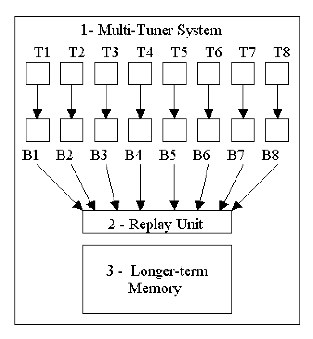
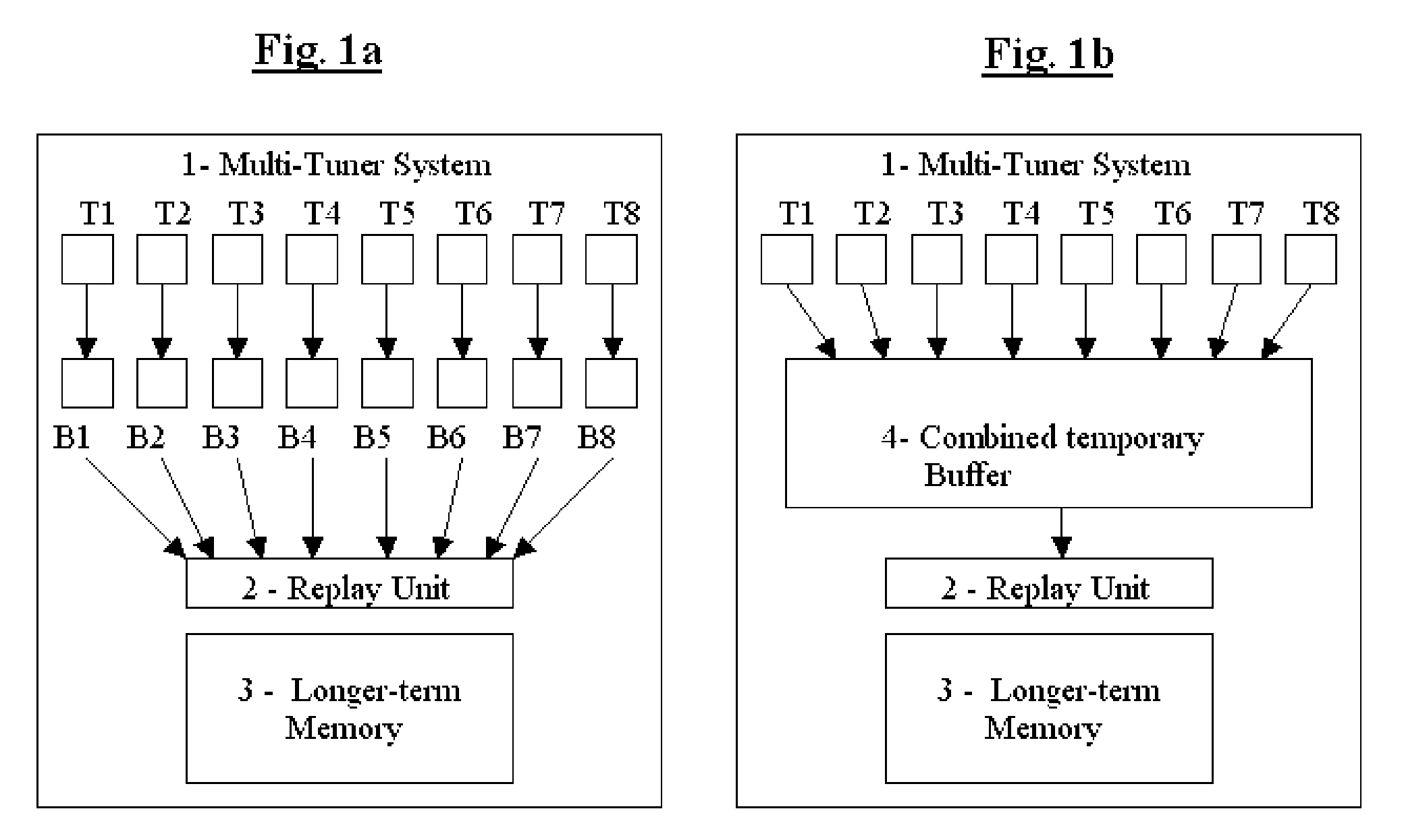
[0026] Referring to FIGS. 1a-b, I show illustrations of preferable examples of a multi-tuner system (1) enabling retroactive recording while zapping between channels. In this example there are 8 available tuners (marked as T1-T8), however this is only an example and of course any other convenient number can also be used. This system can be implemented for example in an Audio tape recorder, or in a Radio tuner or in a device which is a combination of the two, or for example in a Video Recorder, or in a computer, or in other devices. Each Tuner can be for example coupled to its own temporal buffer (marked as B1-B8), as shown in FIG. 1a. This has the advantage of more simplicity and less logic needed, however it has the disadvantage that the user can't divide the memory between the channels according to their importance to him / her. In the version shown in FIG. 1b all the tun...


PUM

PropertyMeasurementUnit
timeaaaaaaaaaa
timeaaaaaaaaaa
timeaaaaaaaaaa

Abstract

One of the most frustrating things when recording for example songs from the radio is that many times by the time the user decides that he / she would like to record for example some song, the beginning of the song is already lost. Or the user might zap between radio stations and tune into the station after the song has already started or for example after the beginning of an interesting conversation or message or News item and is frustrated that he missed the beginning of it. Similarly, for example while zapping through cable TV stations, a user might find for example a fascinating scientific program or a fascinating report and regret that he / she had not seen or recorded it from the start for later reference. The idea of retroactive recording and / or replay has existed already since 1990 and there are a number of patents about it, but they do not deal with the problem of enabling retroactive recording and / or replay also when the user is zapping between channels for example on Radio or on TV. The present invention describes an improved system and method for automatic time-shifted retroactive recording or replay, that applies retroactive recording and / or replay also to a situation of switching between channels. Additional improvements and possible implementations are also shown, including for example improved zapping speed which can be used also without retroactive replay / recording.

Description

[0001] This patent application is a CIP of U.S. application Ser. No. 10 / 449,703 of Jun. 2, 2003, hereby incorporated by reference in its entirety, which claims priority from Israeli application 149968 of May 31, 2002 and from U.S. provisional application 60 / 439,999 of Jan. 10, 2003, hereby incorporated by reference in their entireties.[0002] This patent application also claims priority from Canadian application 2,451,945 of Dec. 12, 2003, hereby incorporated by reference in its entirety. BACKGROUND OF THE INVENTION [0003] 1. Field of the Invention [0004] The present invention relates to retroactive recoding or replay, and more specifically to an improved system and method for automatic time-shifted retroactive recording or replay, so that when the user requests for example an audio tape recorder or a video tape recorder to start recording, he / she may also request that the recording will be retroactive, i.e. for example to start as if the user had requested it before, for example a f...

Claims


Application Information

Patent Timeline
Patent Type & Authority Applications(United States)
IPC IPC(8): G04F1/04G10H1/18G10H3/12G11B5/00H04NH04N5/76H04N5/761H04N5/781
CPCG11B15/026H04N9/8211G11B31/003G11B31/006G11B2020/10592G11B2020/10666G11B2020/10944G11B2020/10962G11B2220/60G11B2220/90H04H60/27H04H60/74H04H2201/60H04N5/782H04N5/783H04N9/8042G11B20/10527
Inventor MAYER, YARON
Owner MAYER YARON
Why Eureka
Try Eureka