Sight and sight pins for archery bow

a technology for sighting pins and archery bows, which is applied in the direction of sighting devices, white arms/cold weapons, weapons, etc., can solve the problems of dimmer sight points, devices that fail to support and maintain fiber optic strands along their entire length, and prior art devices suffer from a number of deficiencies, so as to enhance the ability of intermediate range targeting, enhance the sighting point, and the effect of more precise means

Active Publication Date: 2005-07-14
BLACK GOLD ARCHERY LLC
View PDF26 Cites 22 Cited by
  • Summary
  • Abstract
  • Description
  • Claims
  • Application Information

AI Technical Summary

Benefits of technology

[0011] The guard is removably fixed to the base. The guard is generally shaped to encircle the targeting axis of the sight pins and thereby offers protection to the sight pins. The guard includes a plurality of light-gathering fibers spaced about the outer diameter of the guard. The fibers provide points of reference by which the archer may center or align the sighting device by reference to the field of sight of the peep. Moreover, the fibers allow the archer to utilize a large peep in low-light conditions.
[0012] The sight pins include a light-gathering fiber and an offset-Y-shaped fiber support. The light-gathering fiber comprises a length of light-gathering fiber optic material. The entire length of the fiber is maintained in a straight line along the targeting axis. The offset-Y-shaped fiber support is defined by a clasped end and a cubed end. The cubed end is a cube shaped segment which is sized for a mating engagement in either of the arcuate channels of the base. The clasped end of the offset-Y-shaped fiber support is sized to support the entire length of the light-gathering fiber. From cubed end to clasped end, the offset-Y-shaped fiber support takes on a offset-Y-shaped configuration. The offset dimension is equivalent to the spacing between the arcuate channels such that by rotating the offset-Y-shaped fiber support 180 degrees about its longitudinal axis, the sight pins may be placed in either of the arcuate channels while maintaining the targeting axis position of the sight points. The sighting points are located at each distal end of each light-gathering fiber and are of larger diameter than the remainder of the fiber. Additionally, an enhanced sighting point may be provided at each distal end of the light-gathering fiber to enhance intermediate range targeting ability and to provide the archer with more precise means for directionally aligning the sight pins, i.e., for discerning either unwanted torqueing or canting of the bow.

Problems solved by technology

However, the prior art devices suffer from a number of deficiencies.
First, the prior art devices either fail to support and maintain the fiber optic strand in a strait line along its entire length.
Whenever a light-gathering fiber is bent, light leaks out resulting in a dimmer sight point.
Moreover, any portion of the delicate light-gathering fiber extending outside the support is subject to potential breakage.
Second, the prior art sighting devices fail to compensate for the vertical spacing of the numerous sight pins.
Third, prior art devices fail to provide a centering system for low-light usage.

Method used


Image

  • Sight and sight pins for archery bow
  • Sight and sight pins for archery bow
  • Sight and sight pins for archery bow

Examples


Embodiment Construction

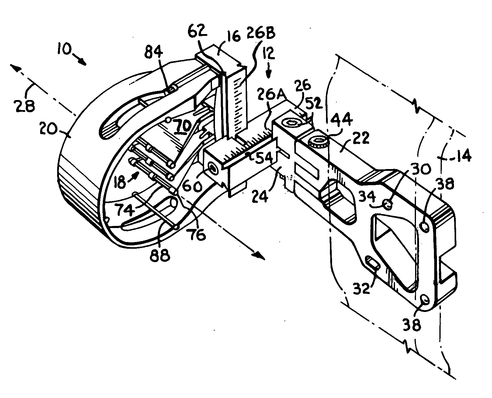
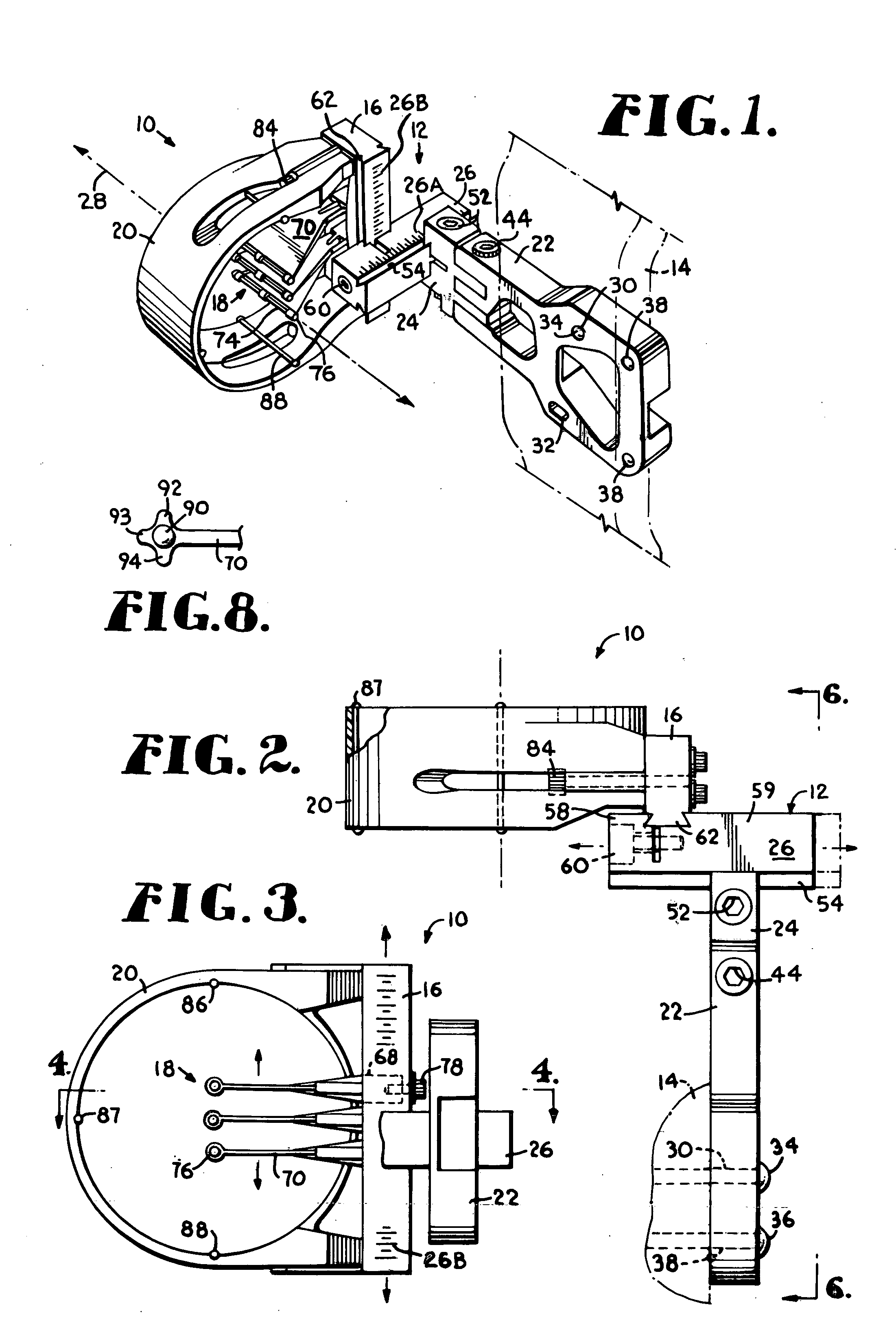
[0023] Referring now to the drawings in detail, and initially to FIG. 1, numeral 10 generally designates a sighting device constructed in accordance with a first embodiment of the present invention. As best seen in FIG. 3, device 10 generally includes a sighting assembly including a base 16, sight pins 18, and a guard 20. As best seen in FIG. 2, device 10 also includes a mounting assembly 12 for attaching the sighting assembly to a bow.

[0024] As best seen in FIG. 1, the mounting assembly 12 includes a bow-mount portion 22 and a horizontal beam 26. For point of reference, the targeting axis defines a targeting axis line 28. The horizontal beam 26 of the mounting assembly 12 includes a horizontal beam channel 62 that is slidingly engaged to base 16. The horizontal beam channel 62 is secured to base 26 by tightening of horizontal beam locking screw 60. This arrangement allows for vertical adjustment of the sighting assembly relative to the bow. Additionally, the bow-mount portion 22 o...


PUM


Abstract

A device used to facilitate the accurate shooting of an archery bow. The device includes horizontally and vertically adjustable support structure for attaching the device to a bow. Moreover, the device includes a base, a guard and sight pins. The base includes arcuate channels sized for receipt of sight pins and arched to ensure that the sight pins are aimed at the archer's eye regardless of vertical spacing. The sight pins include an offset-Y-shaped fiber support and a light-gathering fiber. The light-gathering fiber comprises a length of fiber optic material with a sighting point on each distal end thereof. The offset-Y-shaped fiber support is an offset-Y-shaped member whose offset allows for placement in either of two spaced arcuate channels while maintaining the targeting axis position of the sighting points. The guard, which encircles the sight pins, includes three fiber optic fibers spaced about its diameter to allow for low-light alignment.

Description

CROSS REFERENCE TO RELATED APPLICATIONS [0001] Not applicable. STATEMENT REGARDING FEDERALLY SPONSORED RESEARCH OR DEVELOPMENT [0002] Not applicable. BACKGROUND OF THE INVENTION [0003] The present invention relates to a device used to facilitate the accurate shooting of an archery bow. More particularly, the invention relates to a sighting device comprising a sight structure and sight pins. Bow sights typically consist of a support structure used to secure a sighting device to a bow and a plurality of vertically spaced sight points attached to horizontal pins. Each of the different sight points represent distinct target ranges. By selecting the appropriate pin and sight point for a given range, the archer can accurately aim his arrow for a specified target distance. [0004] The use of a bow for hunting or target practice often occurs in low-light conditions when visibility of a sight point is critical. Various sighting devices have been developed to gather ambient light to improve vi...

Claims


Application Information

Patent Timeline
Patent Type & Authority Applications(United States)
IPC IPC(8): F41G1/467
CPCF41G1/467
Inventor ELLIG, MICHAELMURRAY, JEFF
Owner BLACK GOLD ARCHERY LLC
Why Eureka
Try Eureka