One piece catalytic converter with integral exhaust manifold

a catalytic converter and exhaust manifold technology, applied in the field of catalytic converters, can solve the problems of multiple parts assembling to arrive at a useful component, inherent gas leak path of multi-piece components,

Inactive Publication Date: 2005-07-14
WESCAST USA
View PDF9 Cites 70 Cited by
  • Summary
  • Abstract
  • Description
  • Claims
  • Application Information

AI Technical Summary

Problems solved by technology

Among the perceived drawbacks to this type of catalytic converter assembly are the costs associated with assembling multiple pieces to arrive at a usef

Method used


Image

  • One piece catalytic converter with integral exhaust manifold
  • One piece catalytic converter with integral exhaust manifold
  • One piece catalytic converter with integral exhaust manifold

Examples


Embodiment Construction

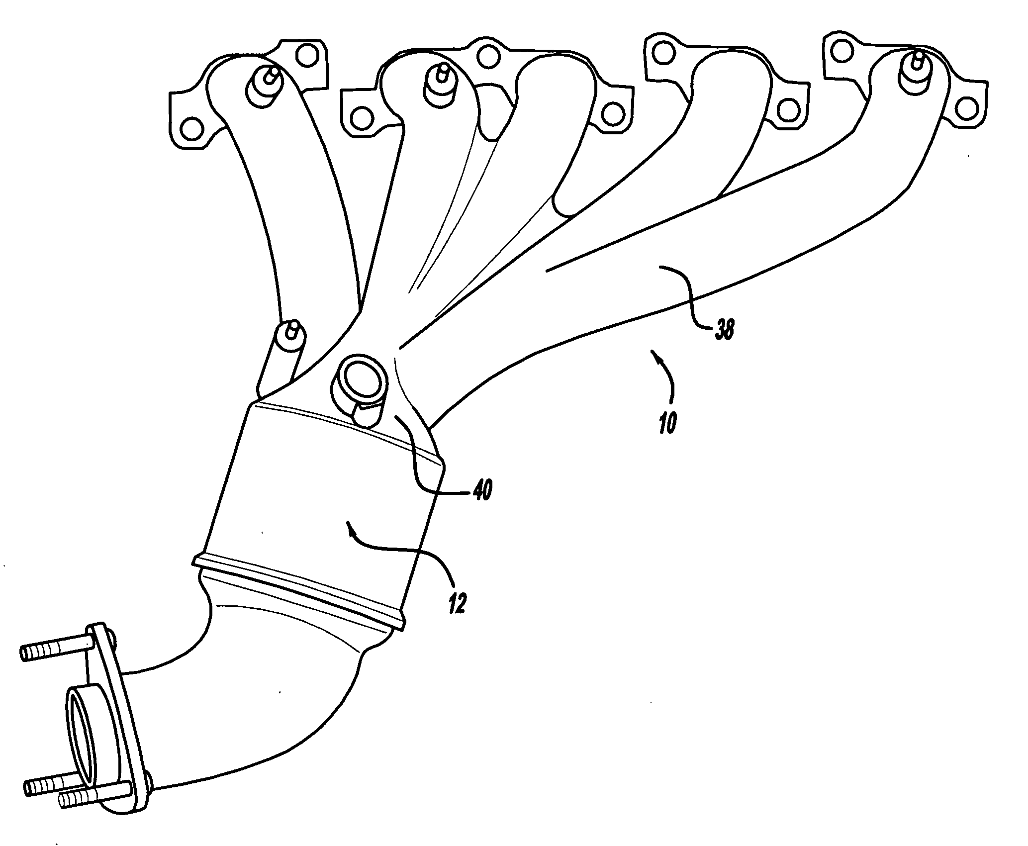
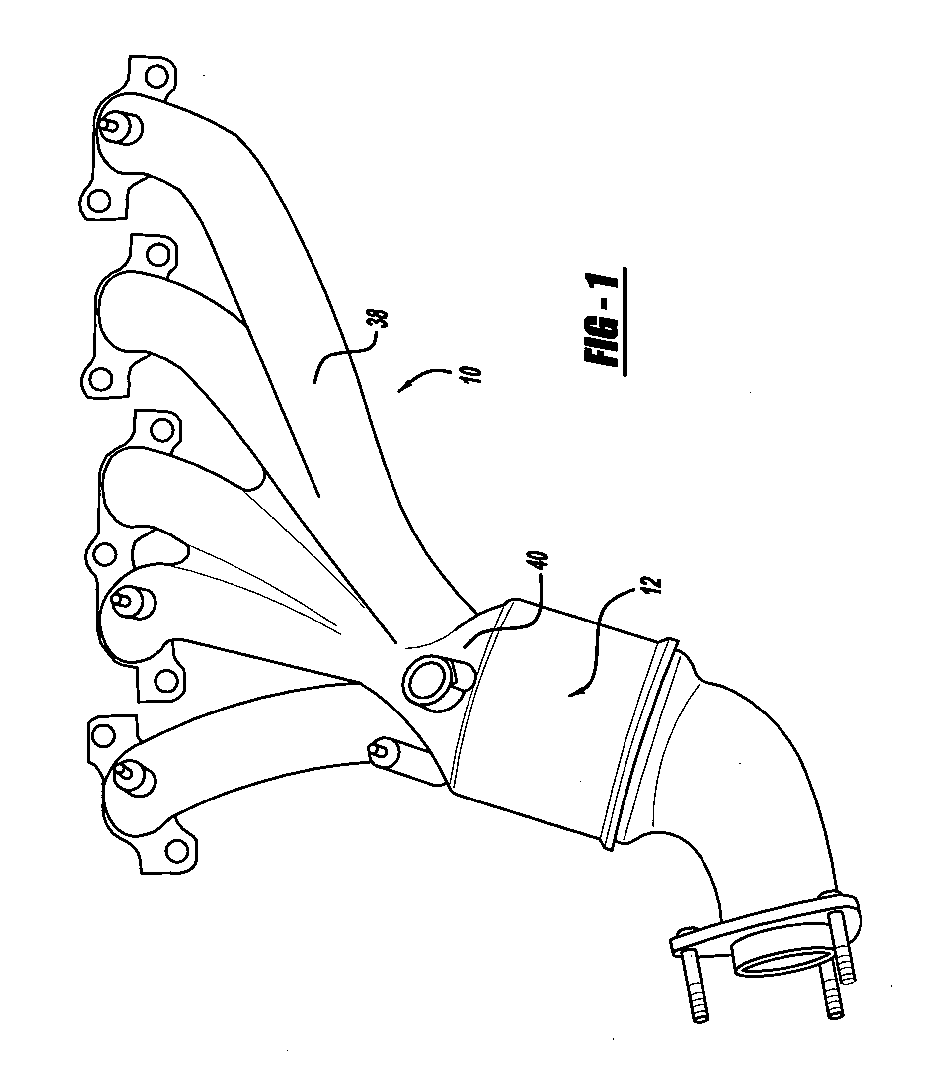
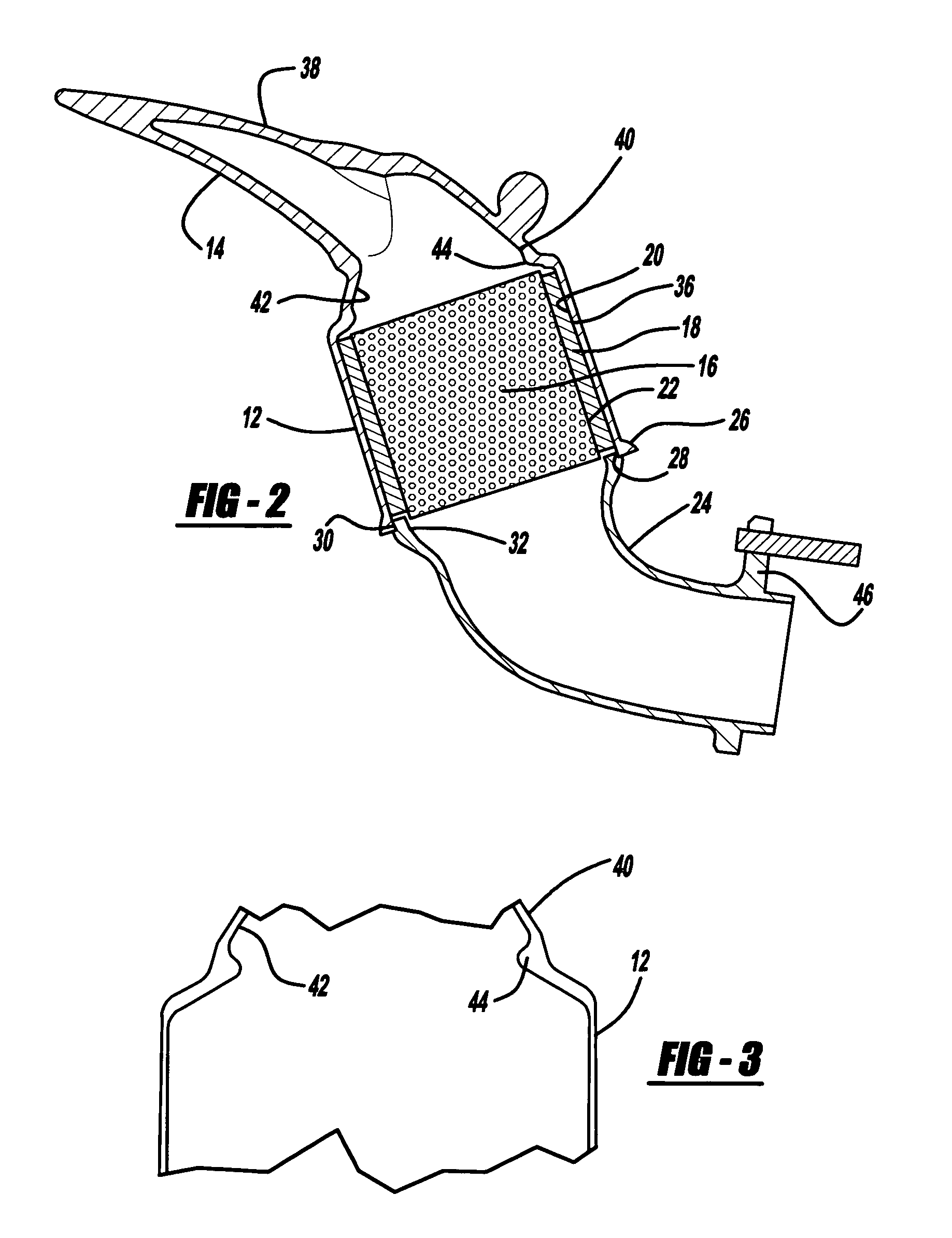
[0012] Referring to FIGS. 1 and 2, shown is a catalytic converter assembly 10 employing a one piece catalytic converter can and integral manifold assembly. The converter can portion is defined by reference numeral 12 and the manifold is defined by reference numeral 14. Generally, the catalytic converter can portion 12 houses the components necessary for converting the exhaust gases prior to discharge from the vehicle to the atmosphere. While not specifically shown, the converter can and / or the manifold portion of the assembly can be provided with various sensors to monitor gas flow through the system.

[0013] As illustrated, the catalytic conversion components inserted within the converter can portion 12 include a substrate 16 which is held in place by a mounting mat 18. Z-seals (not shown) which are known in the art, may be used in association with the mat to assist in securing the substrate within the converter can. The mounting mat is disposed adjacent the inner wall 34 of the con...


PUM


Abstract

The present invention relates to exhaust system assemblies and, more particularly, to a one piece catalytic converter can with an integral exhaust manifold. Disposed within the catalytic converter can are the catalytic conversion components. Coupled to the one piece converter can and integral exhaust manifold is a second end cone to provide a substantially air tight seal to the assembly.

Description

CROSS-REFERENCE TO RELATED APPLICATIONS [0001] This application claims the benefit of U.S. Provisional Application No. 60 / 533,233, filed on Dec. 30, 2003. The disclosure(s) of the above application(s) is (are) incorporated herein by reference.FIELD OF THE INVENTION [0002] 1. Technical Field [0003] The present invention relates to catalytic converters and, more particularly to a one piece catalytic converter can with an integral exhaust manifold. Preferably the integral catalytic converter can and exhaust manifold are formed as a unitary casting. While numerous materials may be suitable for casting the one piece catalytic converter and exhaust manifold, cast irons and, preferably SiMo cast irons are preferred. [0004] In addition to the one piece catalytic converter with integral exhaust manifold, the present invention also relates to a method of welding an end cone to the one piece catalytic converter and integral exhaust manifold. [0005] 2. Discussion of Prior Art [0006] Catalytic c...

Claims


Application Information

Patent Timeline
IPC IPC(8): F01N3/00F01N3/10F01N3/24F01N3/28F01N13/10
CPCF01N3/24F01N13/10F01N3/2857
Inventor KALISH, MARTIN W.PURDY, ROBERT B.MCALLISTER, CLINTON J.
Owner WESCAST USA
Why Eureka
Try Eureka