Traveling crane and assembling/disassembling method thereof

a technology of travel cranes and support legs, which is applied in the direction of cranes, etc., can solve the problems of physical facilities breaking, disadvantages in operating efficiency and cost overrun due to additional sheave, and weight in the vicinity of the boom end (around the strut), so as to avoid the interference between the obstacles and the support legs

Active Publication Date: 2005-07-14
KOBELCO CONSTR MASCH CO LTD
View PDF5 Cites 19 Cited by
  • Summary
  • Abstract
  • Description
  • Claims
  • Application Information

AI Technical Summary

Benefits of technology

[0031] In this case, the support legs and the support leg guide members may be partially provided in the spreader and on the boom upper surface, as well as at positions capable of avoiding obstacles, so that the interference between the obstacles and the support legs can be readily...

Problems solved by technology

In this method, there has been a problem that a dedicated guide sheave for assembling/disassembling must be provided at an end of a rear member constituting a strut for moving the upper spreader, so that the weight in the vicinity of the boom end (around the strut) becomes larger, having disadvantages in operating efficiency and in cost overrunning due to the additional sheave.
On the other hand, when the jib derricking rope is rewound (being wound during disassembling) while the hook-hoisting rope is wound (being rewound during disassembling), since the synchronization of both the ropes depends on manual operation of an operator, there have been problems due to asynchrony that both the ropes may tear off or a physical faci...

Method used


Image

  • Traveling crane and assembling/disassembling method thereof
  • Traveling crane and assembling/disassembling method thereof
  • Traveling crane and assembling/disassembling method thereof

Examples


first embodiment (see figs.1 to 9)

First Embodiment (See FIGS. 1 to 9)

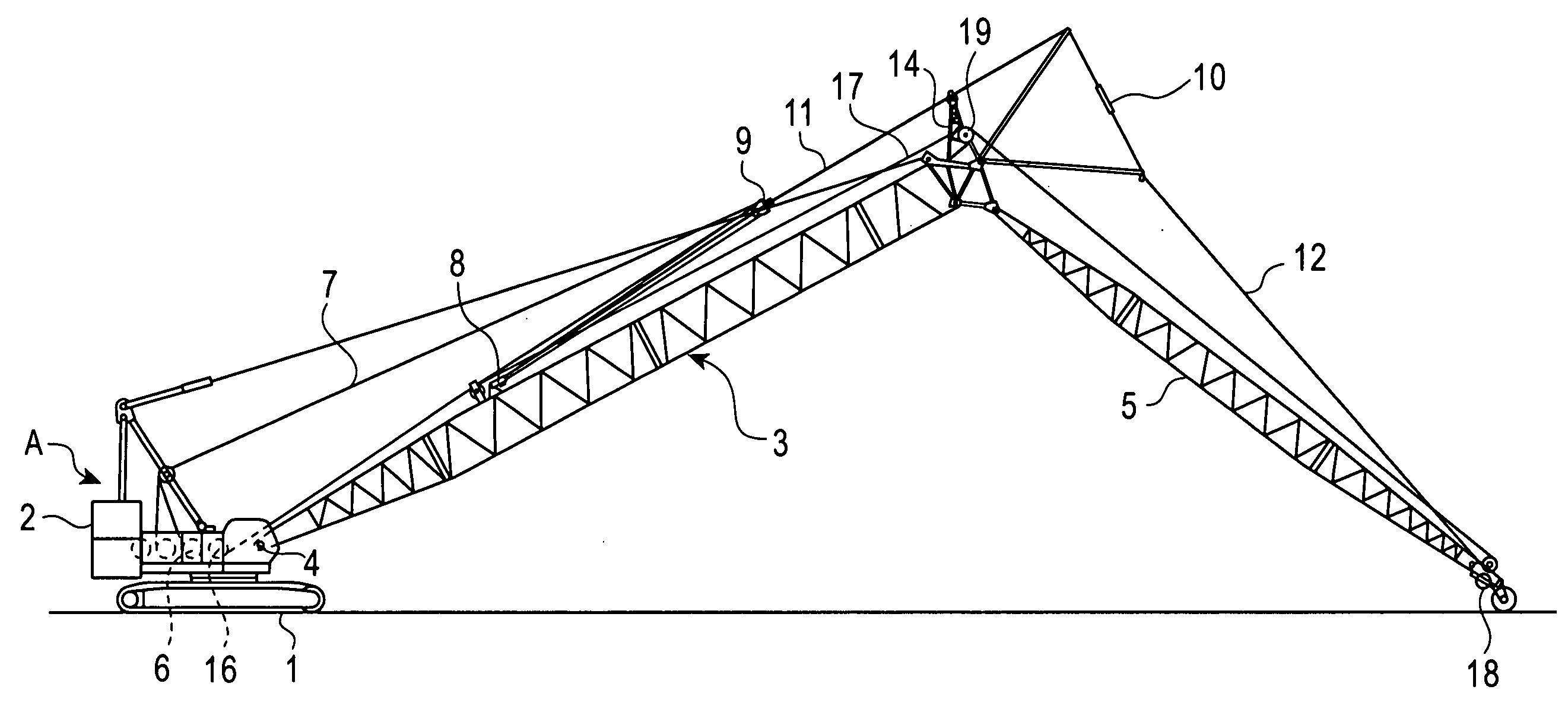
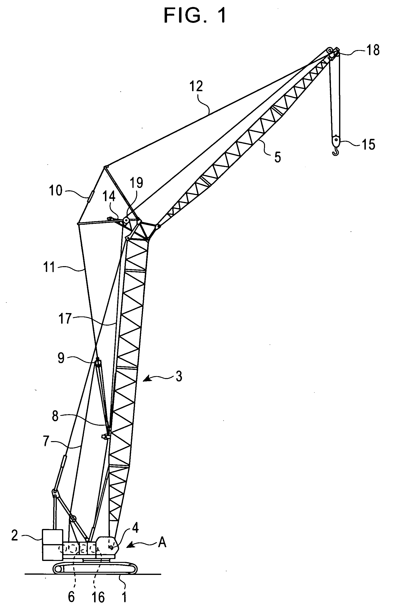
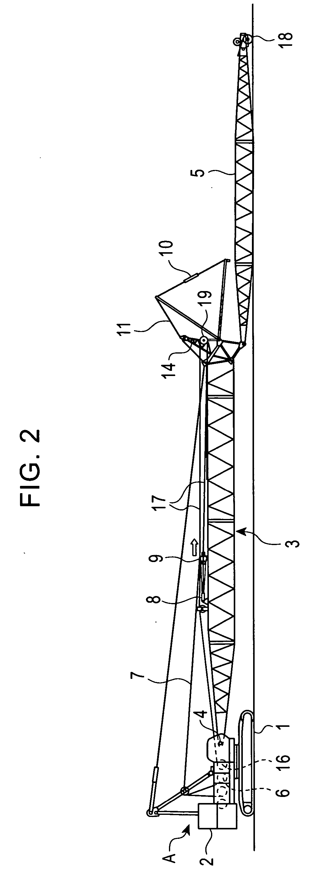
[0049]FIG. 1 shows an operation state (assembled state) of a traveling crane according to the present invention; FIGS. 2 to 7 show the procedure of assembling / disassembling of the crane.

[0050] In the drawings, on a crawler lower traveling body 1, an upper rotating body 2 is revolvably mounted so as to constitute a base machine A therewith. On the upper rotating body 2, a boom (may also be called as a tower depending on a specification) 3 is derrickably mounted so as to be raised and lowered with a boom foot bin 4 as a derricking fulcrum. At a far end of the boom 3, a jib 5 is derrickably attached.

[0051] In addition, there may be a crane that is operated by derricking both the boom 3 and the jib 5; the present invention may incorporate a traveling crane of this type.

[0052] Fundamentally, in a state that the boom 3 is maintained at a predetermined angle, the crane is operated by derricking the jib 5 (in a luffing crane, the boom 3 is also derricke...

second embodiment (see fig.10)

Second Embodiment (See FIG. 10)

[0096] According to the first embodiment, the operation is restricted only in the direction that the tension of the jib derricking rope 7 increases. Conversely, the excessively decreased rope tension may cause the irregular winding, so that it is desirable that the operation be restricted also in the direction that the rope tension decreases.

[0097] The control according to a second embodiment having these two functions will be described with reference to FIG. 10.

[0098] It is determined: at Step S11, whether an assemble / disassemble mode is selected or not; at Step S12, whether the boom angle is the angle during the assembling / disassembling or not. Then, at Step S13, it is determined whether simultaneous operations of the rewinding of the jib derricking rope and the winding of the hook hoisting rope is carried out based on signals from the pressure sensors 32 and 33 shown in FIG. 8 or not. Thereafter, the operation in the direction that the rope tensio...

third embodiment (see figs.11 to 15a)

Third Embodiment (See FIGS. 11 to 15A)

[0111] An upper spreader 9′ structured differently from that according to the embodiments described above and a structure for moving the upper spreader 91 between the boom anchor and the leading end of the boom will be described with reference to FIGS. 11 to 14. On the other hand, structures common to the embodiments described above will be described with reference to the above-mentioned figures.

[0112] Along a predetermined section within between the anchor of the boom 3 and the leading end thereof, a lateral pair of rails 190 and 190 are provided on the boom upper surface.

[0113] Both the respective rails 190 and 190 are formed in a closed section having a horizontal upper surface, such as a square steel pipe.

[0114] On the other hand, the upper spreader 9′ is integrally composed of a vertical sheave block 220 having a plurality of (two in the drawing) vertical sheaves 210 and 210 rotating about a horizontal sheave shaft 200 and a horizontal s...


PUM


Abstract

A traveling crane according to the present invention includes a hook hoisting guide sheave for guiding a hook hoisting rope from the top of a boom toward the end of a jib, and the hook hoisting guide sheave is arranged on the top of the boom in a state that the guide sheave can guide the hook hoisting rope along the upper surface of the boom by folding the rope toward an upper spreader placed at a position adjacent to a boom anchor during assembling/disassembling of the crane. Thereby, the upper spreader can be moved between the boom anchor and a far end of the boom without providing a guide sheave dedicated for moving the upper spreader. Pairs of support legs are downward provided on both sides and in front and in rear of the upper spreader and a roller is provided for each support leg, so that interference between the upper spreader during movement and obstacles on the boom upper surface can be prevented even in a horizontal movement system excellent in operating efficiency.

Description

BACKGROUND OF THE INVENTION [0001] 1. Field of the Invention [0002] The present invention relates to a traveling crane having a jib derrickably attached at an end of a boom and an assembling method thereof. [0003] 2. Description of the Related Art [0004] For transportation to a work site, a large scale traveling crane is divided into a crane body, attachments, such as a boom and a jib, and components of derricking (raising and lowering) devices for the attachments, so that these divisions are assembled on the work site. [0005] Among lower and upper spreaders around which a jib derricking rope is routed, the upper spreader is necessary to be drawn and to be pulled back during disassembling; since the upper spreader is heavy to be moved by man power, the drawing and pulling back during disassembling of the upper spreader are performed using a hoisting force of a winch. [0006] For example, a technique disclosed in Japanese Unexamined Patent Application Publication No. 11-292471 using a...

Claims


Application Information

Patent Timeline
IPC IPC(8): B66C23/34B66C23/36B66C23/66B66C23/82
CPCB66C23/82B66C23/344
Inventor TOUDOU, OSAMUSHIMOMURA, KOICHIFUKUMOTO, KEISUKE
Owner KOBELCO CONSTR MASCH CO LTD
Why Eureka
Try Eureka