Apparatus for driving and adjusting flaps hinged to an aircraft

a technology for adjusting the flap and the aircraft, which is applied in the direction of the position indicator of the movable aircraft element, the aircraft power plant, transportation and packaging, etc., can solve the problems of difficult installation, redundancy of the drive components required for the above conventional flap drive, and duplication of the number of drive units

Active Publication Date: 2005-07-14
AIRBUS OPERATIONS GMBH
View PDF29 Cites 53 Cited by
  • Summary
  • Abstract
  • Description
  • Claims
  • Application Information

AI Technical Summary

Benefits of technology

[0016] The additional differential gear permits generating an r.p.m. difference between the r.p.m.s of neighboring flaps, whereby a different adjustment is individually possible for each flap of a pair.

Problems solved by technology

Such an asymmetric aircraft configuration may, for example, occur when an aircraft engines fails.
Conventional control mechanisms of this type leave room for improvement with regard to the independent adjustment of individual flaps since conventionally such adjustments are generally not possible.
However, such devices require the duplication of the number of drive units and of the rotational shaft drive trains.
The redundancy of drive components required for the above conventional flap drives is a considerable disadvantage since the multitude of drive units including rotational shaft drive trains increases the weight of the aircraft due to the installation of a second central drive unit with its drive train and diverse additional gears and drive shafts which also require additional space and makes installation difficult.
Moreover, drive mechanisms with decentralized individual drives that are mechanically decoupled from one another have the disadvantage that when dimensioning these drives the designer must take into account that any one of these individual drives may fail.
This requirement normally leads to over-dimensioning these redundant drives which in turn results in heavier drive elements.

Method used


Image

  • Apparatus for driving and adjusting flaps hinged to an aircraft
  • Apparatus for driving and adjusting flaps hinged to an aircraft

Examples


Embodiment Construction

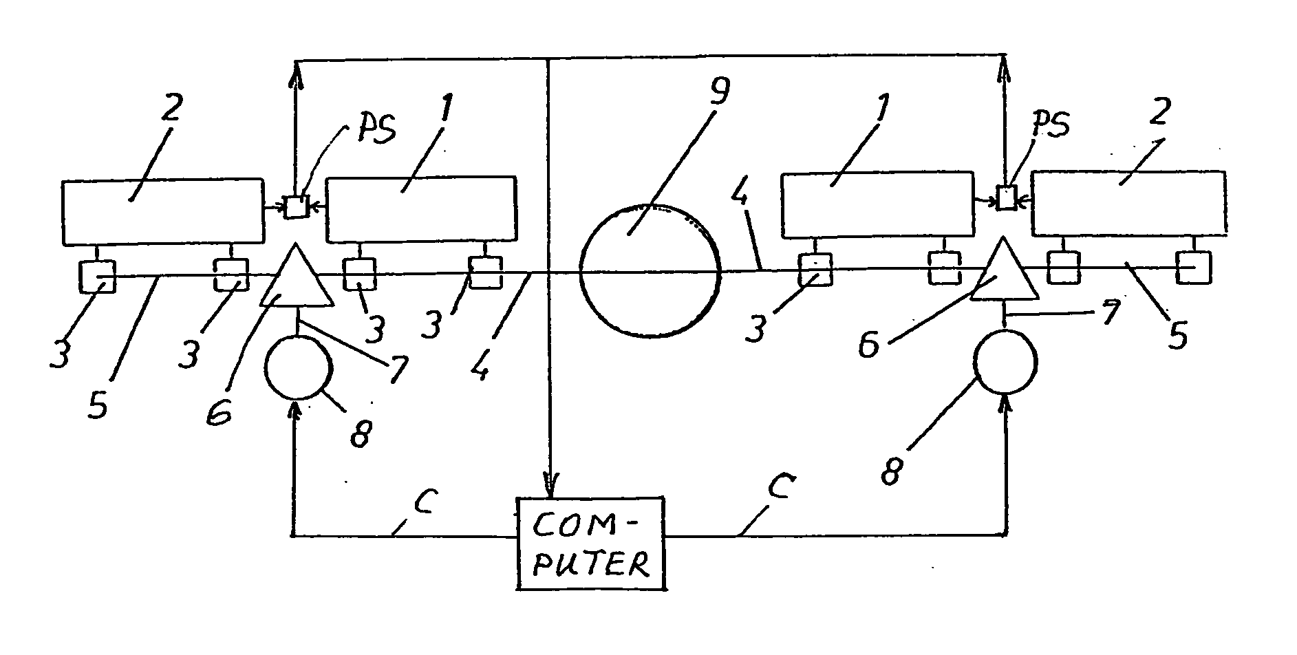
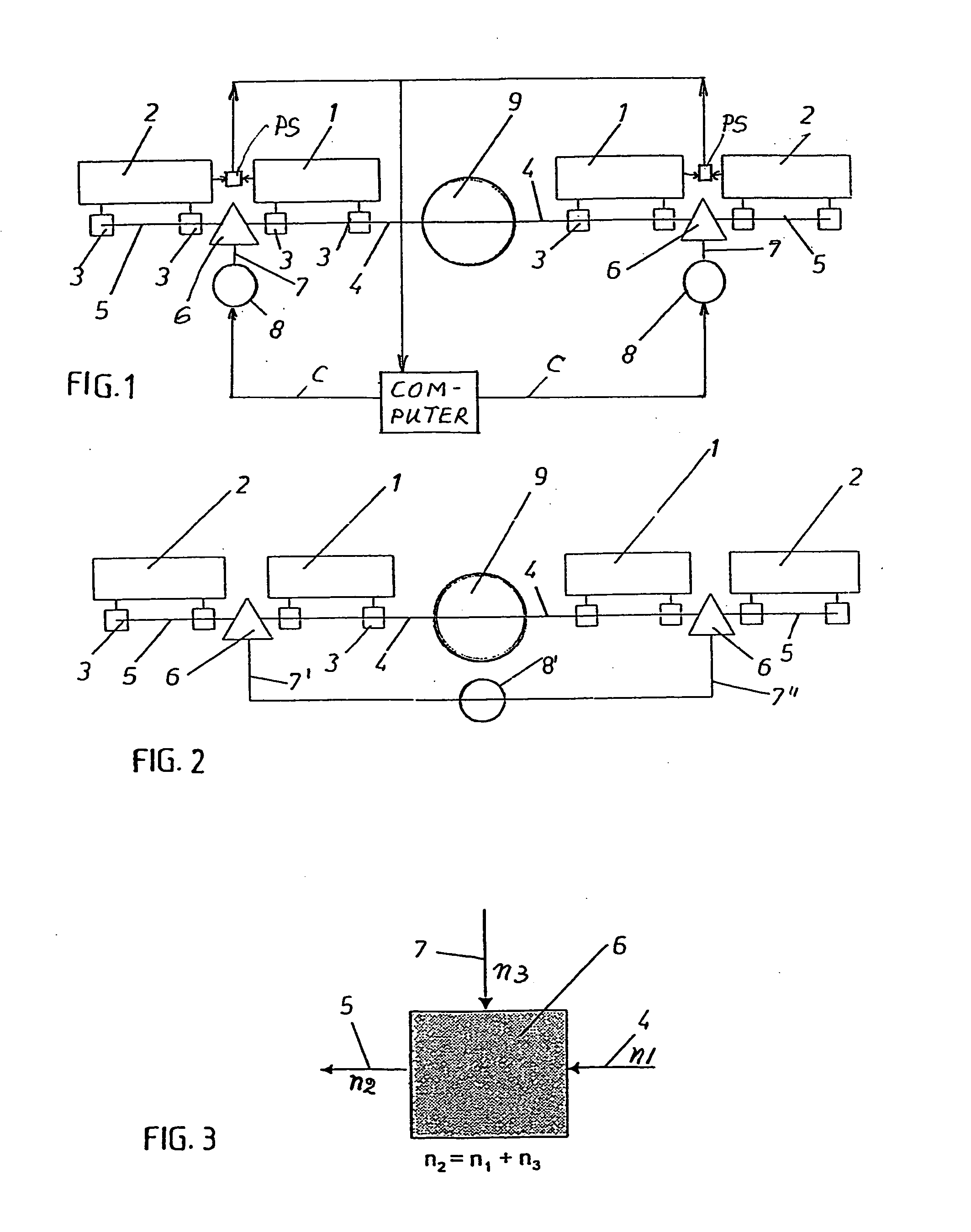
[0023]FIG. 1 shows schematically a pair of flaps 1 and 2 secured to the left wing of an aircraft while a pair of flaps 1′ and 2′ are secured to the right wing of an aircraft. The wings are not shown. Each flap 1, 2, 1′ and 2′ is driven through, for example, two allocated drives 3 such as gears coupled to a main drive shaft 4 driven by a main central drive 9 provided in common for driving the flaps of both wings. The main drive shaft 4 is coupled to further drive shaft sections 5 through respective differential gears 6. One secondary drive 8 is provided for each wing. The secondary drives 8 are coupled through respective drive trains 7 to the corresponding differential gear 6. A brake, not shown, is preferably provided for each of the secondary drives 8.

[0024] The r.p.m. of the drive shaft 4 is determined by the given input r.p.m. of the central main drive 9. The r.p.m. of the further drive shaft 5 coupled to the drive shaft 4 through the differential gear 6 is determined by the inp...


PUM


Abstract

Flaps, for example leading edge flaps and/or trailing edge flaps of an aircraft wing, are driven and adjusted by respective drive units. Drive shafts of neighboring flaps are coupled to each other by a differential gear. The differential gear is thus coupled to a main drive shaft which is driven by a main drive unit. Additionally, the differential gear is coupled to a secondary drive unit. The main drive power and the secondary drive power and thus the respective flap motions are super-imposable on each other, which permits operating the flaps independently of each other or in synchronism with each other.

Description

PRIORITY CLAIM [0001] This application is based on and claims the priority under 35 U.S.C. §119 of German Patent Application 103 61 891.0, filed on Dec. 23, 2003, the entire disclosure of which is incorporated herein by reference. FIELD OF THE INVENTION [0002] Flaps that are hinged to an aircraft, particularly to a lift producing component of an aircraft, such as a wing are operated by respective drive units connected to the flaps through drive shafts integrated into the respective aircraft component. BACKGROUND INFORMATION [0003] Drive units for aircraft flaps connected to the leading and / or trailing edges of an aircraft wing convert a rotational movement into a translatory motion, whereby all drive shafts are coupled to a central drive. [0004] Landing flaps hinged to the trailing edge of a wing and flaps for changing the aircraft wing cross-sectional configuration, such as leading edge flaps hinged to the leading edge of the wing, are conventionally operated by devices comprising ...

Claims


Application Information

Patent Timeline
Patent Type & Authority Applications(United States)
IPC IPC(8): B64C13/26B64D45/00
CPCB64C13/26B64D2045/001B64D45/0005
Inventor POHL, ULRICHTHOMAS, CARSTENLULLA, CHRISTIANKLOENNE, MARTIN
Owner AIRBUS OPERATIONS GMBH
Why Eureka
Try Eureka