Fabric knee airbag for high internal pressures

a technology of airbags and knees, applied in the direction of pedestrian/occupant safety arrangements, vehicular safety arrangements, vehicle components, etc., can solve the problems of vehicle occupants' knees being in contact, primary airbags are less effective in protecting the occupants, injuries can occur, etc., and achieve the effect of less rigidity

Inactive Publication Date: 2005-07-14
AUTOLIV ASP INC
View PDF17 Cites 84 Cited by
  • Summary
  • Abstract
  • Description
  • Claims
  • Application Information

AI Technical Summary

Benefits of technology

[0010] The apparatus of the present invention has been developed in response to the present state of the art, and in particular, in response to the problems and needs in the art that have not yet been fully solved by currently available knee airbag systems. Thus, the present invention provides an effective knee airbag constructed of fabric that can engage the knees and lower legs of a vehicle occupant when activated in a collision. A fabric knee airbag provides a less-rigid surface for impact protection than that provided by currently available load distribution panels. A fabric cushion in knee airbag applications is desirable to provide a soft impact surface so an occupant's knees and lower legs are not injured by the activated airbag.
[0015] The loops that are formed in the airbag wall extend toward the interior of the airbag. When viewing the exterior of the inflated airbag, horizontally-running depressions are observable where the loops extend toward the interior of the airbag. The internal tethers are then attached to the side of each oppositely facing internal loop through stitching. The internal tethers could be attached through alternative means, such as bonding, welding, stapling, and the like. The geometry of this loop-in attachment joint reduces the shear load to the tether stitching thread compared to the butt joints employed in the prior art.
[0016] Alternatively, the loops may be formed in the airbag wall to extend outward, toward the exterior of the airbag. When viewing the exterior of the inflated airbag, horizontally-running loops are observable where depressions would be located on the embodiment utilizing loop-in joints. The internal tether is then attached to the interior of the loop, such that the loop surrounds the internal tether. The internal tether would also be attached by stitching or alternative means as discussed above. The geometry of this loop-out attachment joint also provides superior strength and a reduction in the shear load to the tether stitching thread compared to the butt joints in the prior art.
[0017] According to another alternative, the fabric knee airbag may comprise three internal tethers instead of two for passenger side airbag applications. Passenger side knee airbags may have an additional tether because the airbag usually has a height greater than that of the driver's side knee airbag. Passenger side knee airbags usually have a greater height than their driver's side counterparts because the passenger side knee airbag is typically located under the glove box or low on the instrument panel, which is lower than the location of the driver's side knee airbag on the instrument panel. A greater height ensures that the proper impact protection for a passenger's legs and knees is achieved.
[0021] The fabric knee airbag may also be formed from one continuous fabric sheet that is folded over and sealed on its sides through stitching, or alternatively, welding, bonding, or the like. The continuous fabric configuration provides for excellent hoop strength upon inflation compared to multi-paneled airbags.

Problems solved by technology

When the occupant submarines, the primary airbag is less effective in protecting the occupant.
Such submarining causes the vehicle occupant's knees to contact the instrument panel or structure beneath the panel.
Further injuries can occur when the occupant's legs move forward such that the knees are trapped in or beneath the instrument panel just before the foot well collapses.
As the foot well collapses, the vehicle occupant's feet are pushed backward, which causes the knees to elevate and become further trapped.
As the foot well continues to crush, the load on the trapped legs increase and can cause foot, ankle, and tibia injuries.
Conventional fabric cushions are not normally used in knee airbag applications, without the aid of a load distribution panel because it is difficult to restrain an occupant's lower legs with a conventional fabric airbag.
The lower legs tend to “knife” through the airbag because conventional fabric airbags do not have sufficient internal pressures to withstand such force.
Conventional airbag cushions, such as those used for driver, passenger, or side applications, typically use bag pressures in the range of 4 to 6 pounds per square inch, which is an insufficient pressure to prevent an occupant's knees from knifing through the airbag.
However, load distribution panel designs have several limitations.
One such limitation is that load distribution panel designs often involve complicated systems for attaching the load distribution panel to the airbag, thereby requiring more parts and skill in assembly than non-load distribution panel designs.
The attached load distribution panel also limits the flexibility vehicle manufacturers have in designing the instrument panel because the knee airbag system has a surface area at least the size of the load distribution panel.

Method used


Image

  • Fabric knee airbag for high internal pressures
  • Fabric knee airbag for high internal pressures
  • Fabric knee airbag for high internal pressures

Examples


Embodiment Construction

[0035] The presently preferred embodiments of the present invention will be best understood by reference to the drawings, wherein like parts are designated by like numerals throughout. It will be readily understood that the components of the present invention, as generally described and illustrated in the figures herein, could be arranged and designed in a wide variety of different configurations. Thus, the following more detailed description of the embodiments of the apparatus, system, and method of the present invention, as represented in FIGS. 1 through 8B, is not intended to limit the scope of the invention, as claimed, but is merely representative of presently preferred embodiments of the invention.

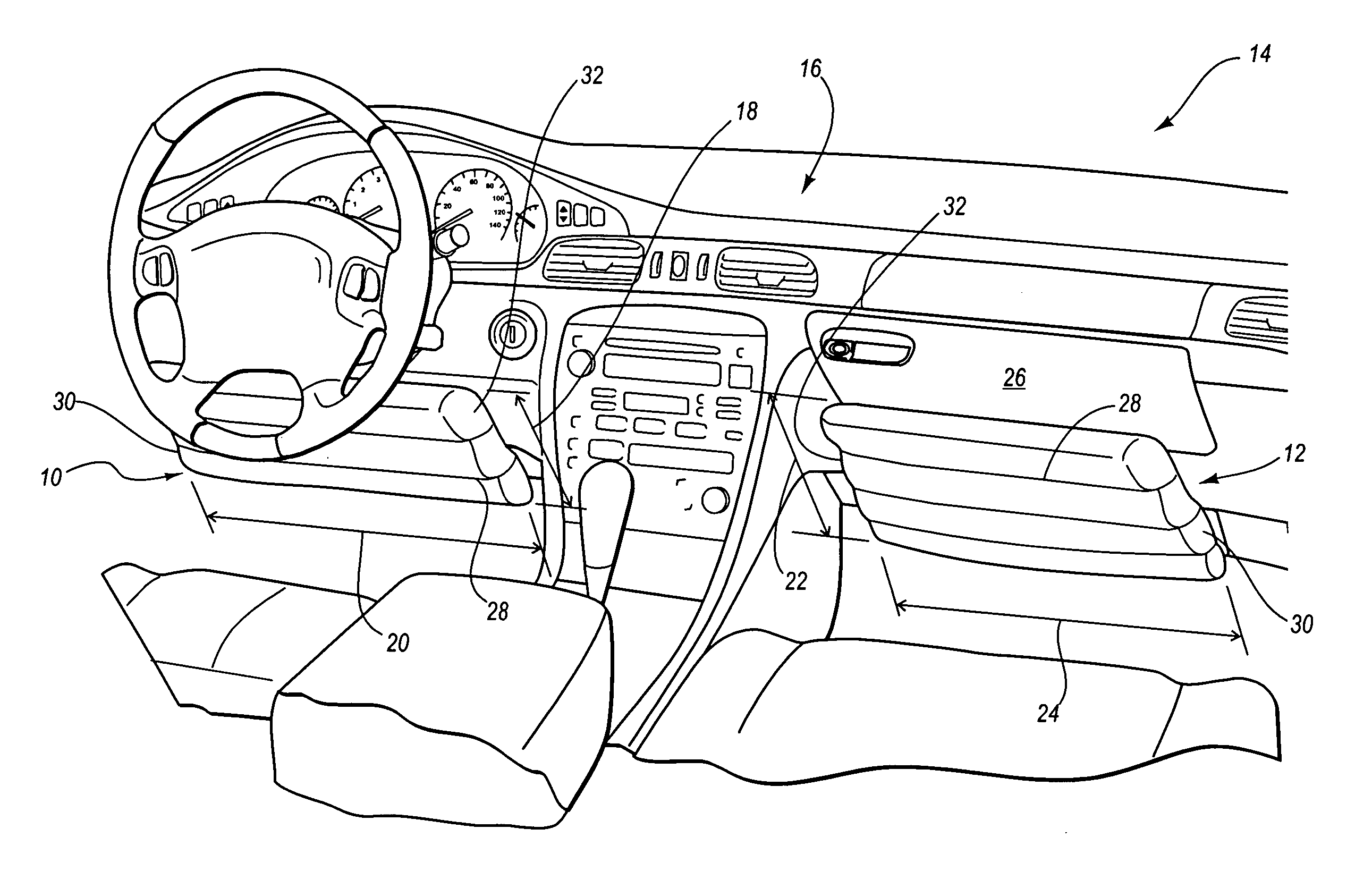
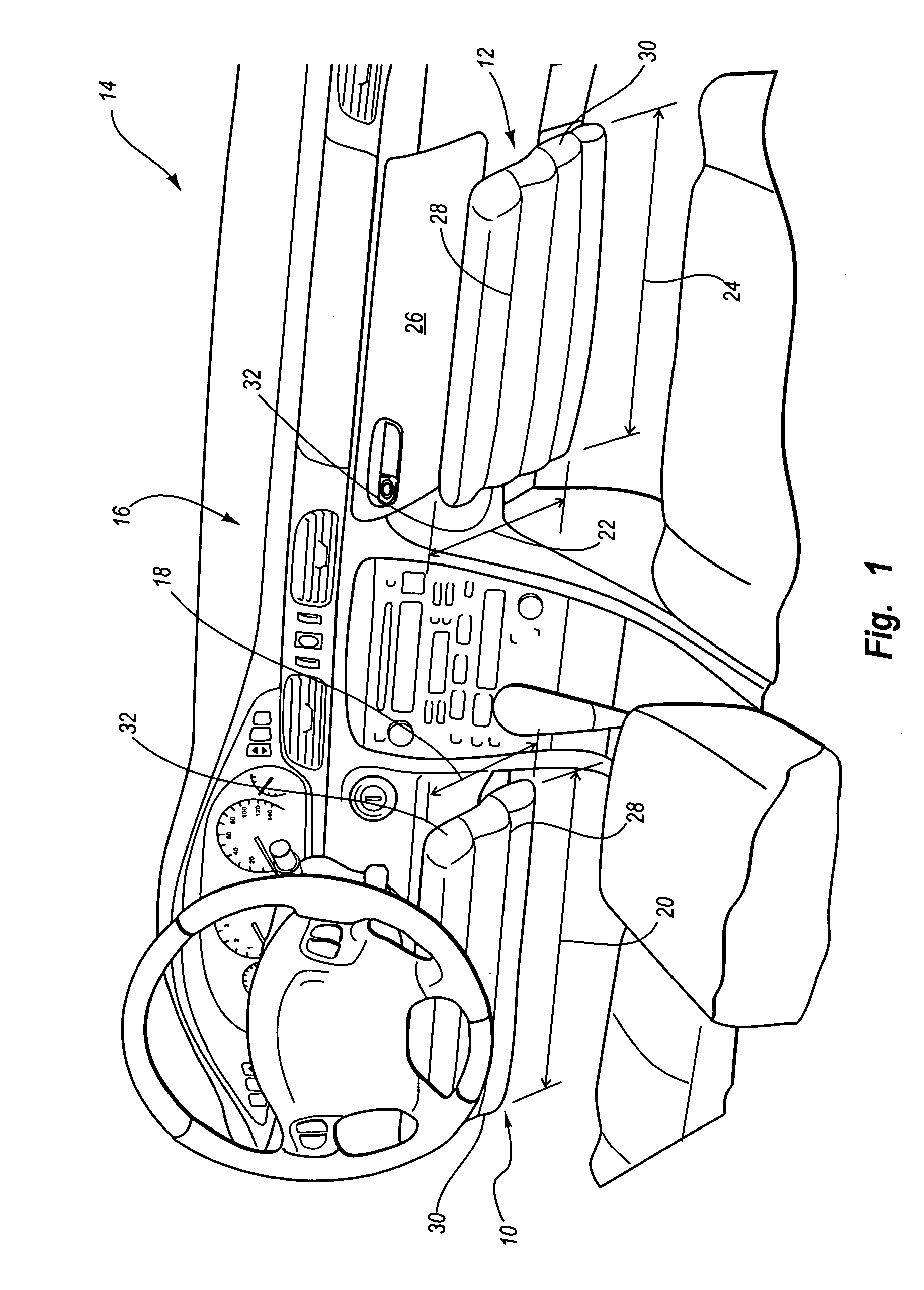
[0036] Referring to FIG. 1, a driver's side knee airbag 10 and a passenger side knee airbag 12 are depicted in an inflated state within a vehicle 14. The knee airbags 10, 12 are constructed of fabric to provide a soft impact surface for the lower extremities of an occupant. The knee...


PUM


Abstract

A fabric knee airbag that is capable of withstanding high internal pressures is provided. The knee airbag is formed from one continuous fabric sheet. The knee airbag has a plurality of loops formed in the walls of the airbag. Internal tethers are disposed within the airbag cushion and are attached to oppositely facing loops. The internal tethers enable the airbag to withstand the high internal pressure by maintaining the airbag at a constant volume and shape upon activation by an inflator. The knee airbag further includes an external tether attached to the exterior of the airbag wall to control the direction of the deployment of the knee airbag.

Description

BACKGROUND OF THE INVENTION [0001] 1. Field of the Invention [0002] The present invention relates to inflatable airbag systems for deployment in front of the knee area of an occupant. More specifically, the present invention relates to fabric knee airbag systems that include internal tether attachments to withstand high internal pressures. [0003] 2. Description of Related Art [0004] Inflatable safety restraint devices, or airbags, are well accepted for use in motor vehicles and have been credited with preventing numerous deaths and injuries. Inflatable airbags are now mandatory on most new vehicles. Airbags are typically installed as part of a system with an airbag module in the steering wheel on the driver's side of a car and in the dashboard on the passenger side of a car. In the event of an accident, a sensor within the vehicle measures abnormal deceleration and triggers the ignition of a charge contained within an inflator. Expanding gases from the charge fill the airbags, which...

Claims


Application Information

Patent Timeline
Patent Type & Authority Applications(United States)
IPC IPC(8): B60R21/00B60R21/16B60R21/206B60R21/233B60R21/2338B60R21/235
CPCB60R21/233B60R21/2338B60R21/235B60R2021/23538B60R2021/23324B60R2021/23386B60R2021/23169
Inventor ENDERS, MARK L.MUELLER, LOUIS A.
Owner AUTOLIV ASP INC
Why Eureka
Try Eureka