
Ink container for an ink jet cartridge

a technology of ink jet cartridge and container, which is applied in printing and other directions, can solve the problems of limiting the degree or rate of absorption of ink into limiting the rate of transfer from the first chamber to and limiting the saturation level maintained in the ink absorbing material. achieve the effect of high saturation level, consistent back pressure, and high ra

Inactive Publication Date: 2005-07-14
NU KOTE INT
View PDF9 Cites 15 Cited by
  • Summary
  • Abstract
  • Description
  • Claims
  • Application Information

AI Technical Summary

Benefits of technology

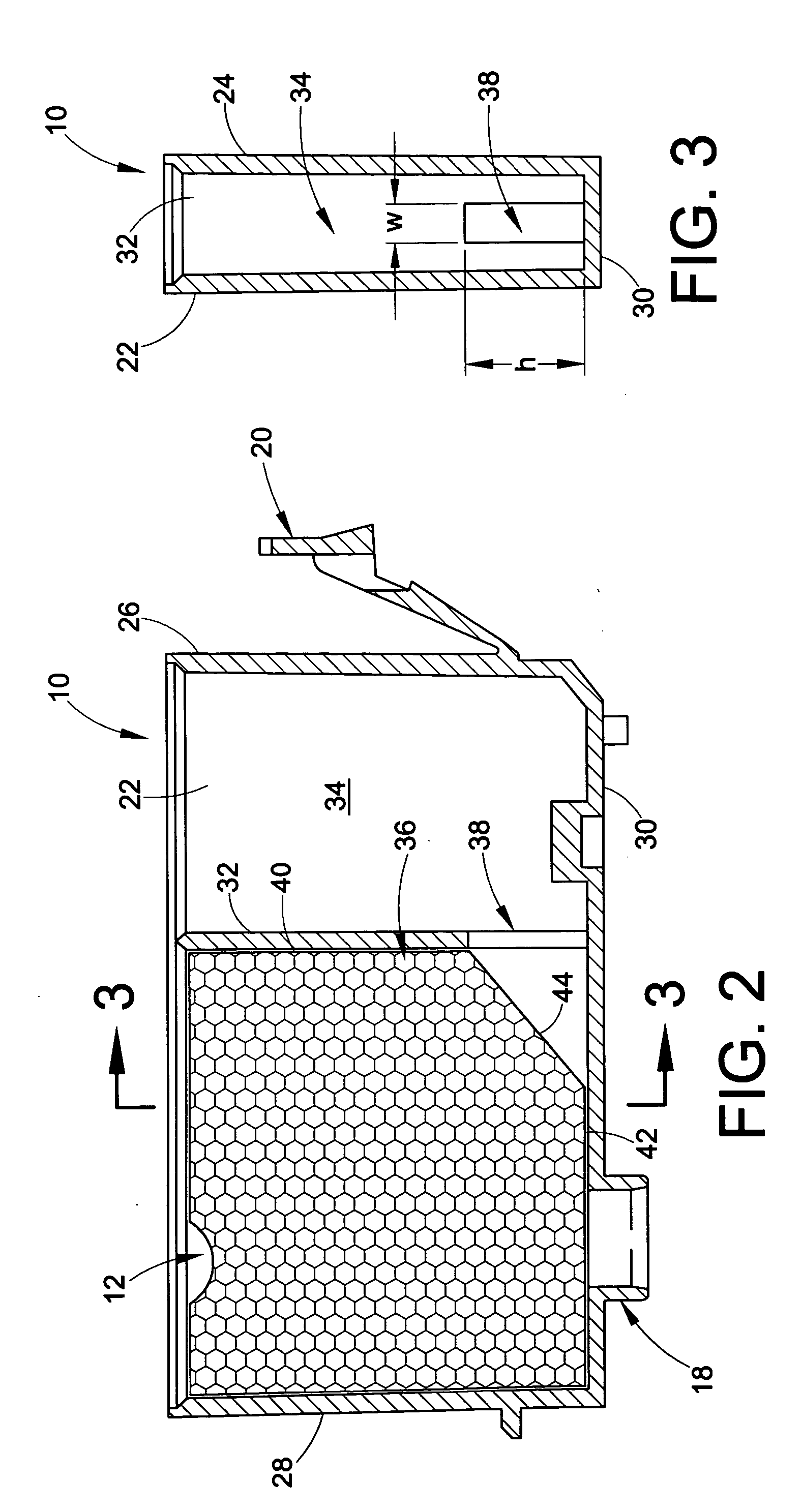
[0006] In accordance with another aspect of the invention, the opening in the partition between the first and second chambers has a geometry which provides the opening with a height above the bottom wall of the container shell which is at least equal to and preferably always greater than the width of the opening. This geometry allows the transfer of liquid to the ink absorbing material at a higher point within the block of material, thus optimizing saturation of the lower portion of the block and allowing the ink absorbing material to maintain a consistently higher saturation level while in the printing mode. The latter enables the ink absorbing material to deliver ink at a higher rate and to maintain a consistent back pressure.
[0015] Yet a further object is the provision of improvements of the foregoing character which promote ease of installation and removal of an ink container relative to a corresponding tank or container holder.

Problems solved by technology

This area relationship limits the transfer rate of ink from the first chamber to the ink absorbing material in the second chamber and also limits the degree or rate of absorption of ink into the ink absorbing material.
Further, the window or opening through the partition heretofore has limited the transfer of ink to the lower most portion of the ink absorbing material in the second chamber, thus limiting the saturation level maintained in the ink absorbing material and, again, limiting the rate of transfer from the first chamber to the ink absorbing material.
The installation arrangement through the interior of the shell is cumbersome and at least somewhat difficult, and the unrestricted movement of the wicking material reduces the capillarity of the ink absorbing material in the region of the wick.
Still further, the lever and tongue arrangement by which the ink container is mountable in and removable from a container holder has sharp edges and irregular surfaces which can be uncomfortable to a user in connection with manipulating the lever during insertion and / or removal of the container from the holder.

Method used


Image

  • Ink container for an ink jet cartridge
  • Ink container for an ink jet cartridge
  • Ink container for an ink jet cartridge

Examples


Embodiment Construction

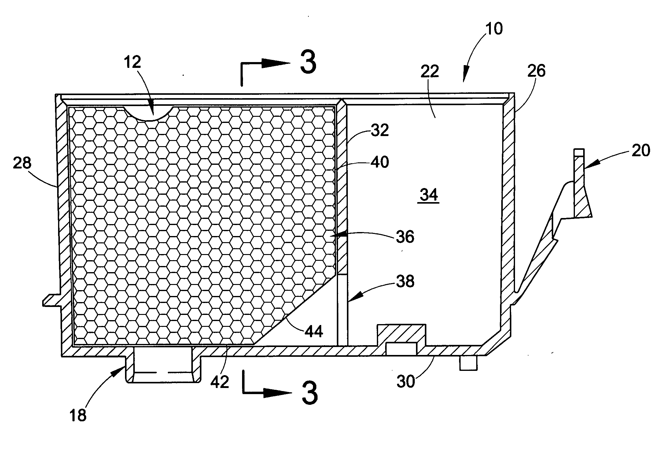
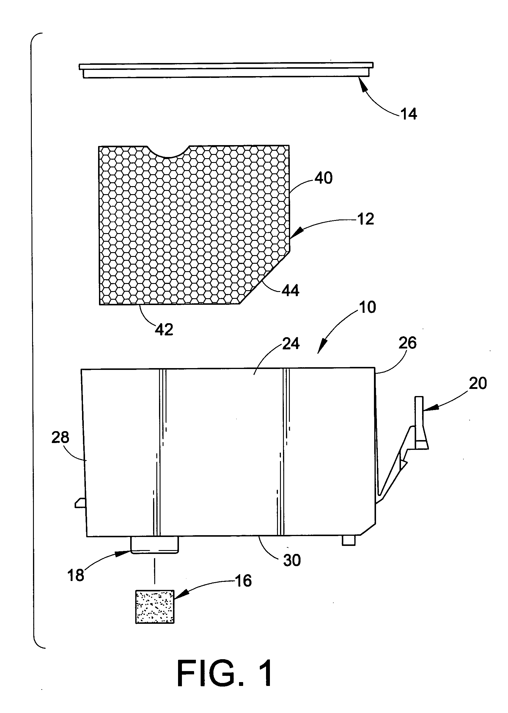
[0025] Referring now in greater detail to the drawings, wherein the showings are for the purpose of illustrating preferred embodiments of the invention only and not for the purpose of limiting the invention, FIG. 1 illustrates the component parts of an ink container for an inkjet cartridge, namely a container shell 10, a block of ink absorbing material 12 such as a urethane foam received in a chamber in the container shell, as will become apparent hereinafter, a cover 14 and a wick element 16 of felt or foam which, as described in greater detail hereinafter, is received in outlet port 18 of the container. Shell 10 includes a lever and tongue component 20 by which the container is adapted to be removably mounted in a container holder.

[0026] As seen in FIGS. 2 and 3 of the drawing, shell 10 comprises a pair of spaced apart side walls 22 and 24, a front wall 26, a rear wall 28, and a bottom wall 30. A partition 32 divides the interior of shell 10 into first and second chambers 34 and ...


PUM


Abstract

An ink container shell for an ink jet cartridge has spaced apart side walls, a front wall, a rear wall, and a bottom wall, a partition in said shell dividing the interior thereof into first and second chambers for respectively receiving an ink and an ink absorbing material, an opening through the partition for communicating ink in said first chamber with ink absorbing material in the second chamber, and which has a height greater than its width. The shell further includes an outlet port in the bottom wall of the second chamber provided with a wick retaining arrangement, and a block of ink absorbing material in the second chamber having an angled surface facing the opening through the partition and having an area greater than the area of the opening. A lever and tongue component for releasably interengaging the container with a holder therethrough has smooth surfaces and edges to facilitate handling of the container.

Description

[0001] This invention relates to the art of ink jet printers and, more particularly, to improvements in ink containers and ink container shells for ink jet cartridges. BACKGROUND OF THE INVENTION [0002] One well-known form of an ink container for ink jet printing comprises a container shell having spaced apart side walls, a front wall, a rear wall, and a bottom wall, a partition in the shell dividing the interior thereof into first and second chambers for respectively receiving an ink and an ink absorbing material, an opening through the partition for communicating ink in the first chamber with ink absorbing material in the second chamber, an outlet port in the bottom wall for the second chamber, a cover closing the upper end of the shell, and a lever attached to the front wall of the shell and which functions to releasably interengage the ink container with a container holder. [0003] In such ink containers and container shells heretofore available, the block of ink absorbing materi...

Claims


Application Information

Patent Timeline
IPC IPC(8): B41J2/175
CPCB41J2/17513
Inventor ANDERSEN, STEPHEN A.LENGYEL, DENNIS M.
Owner NU KOTE INT
Learn More