Methods and apparatus relating to improved visual recognition and safety

Inactive Publication Date: 2005-07-14
TRAYNOR NEIL
View PDF13 Cites 74 Cited by
  • Summary
  • Abstract
  • Description
  • Claims
  • Application Information

AI Technical Summary

Benefits of technology

[0273]FIG. 23b The same configuration as in FIG. 23a but with an additional pair of light str

Problems solved by technology

Emergency workers are often required to work in dangerous conditions where there is no available general light (including sunlight) or extremely low levels of illumination.
However, the problem is obviously most difficult where there is a low level of visibility such as in smoke, silt, rain and other opaque atmospheres or when non-lineal angles of viewing or a line of sight for an observer does not exist or is obscured.
Some incident scenes may not provide a suitable or safe position for the mounting of emergency lights.
Another problem is the glare factor created by a bright intensive light within a dark background.
Often they will wear a miner's type headlight to allow their hands to be free, unfortunately, this means they are often invisible to people behind them.
Fellow workers may find it impossible to identify a ‘Buddy’ team mate because of the high source of glare generated by the other's headlamp or torch in the low levels of light often encountered.
This loss of ‘Night Vision’ may result in placing one's self in additional danger.
A further complication is that it is often difficult for safety workers and others to identify their

Method used


Image

  • Methods and apparatus relating to improved visual recognition and safety
  • Methods and apparatus relating to improved visual recognition and safety
  • Methods and apparatus relating to improved visual recognition and safety

Examples


Embodiment Construction

[0037] The invention will now be discussed in detail by reference to the following Figures and Legend:

Legend

Summary of Numbers Used to Illustrate Drawings

Number Description

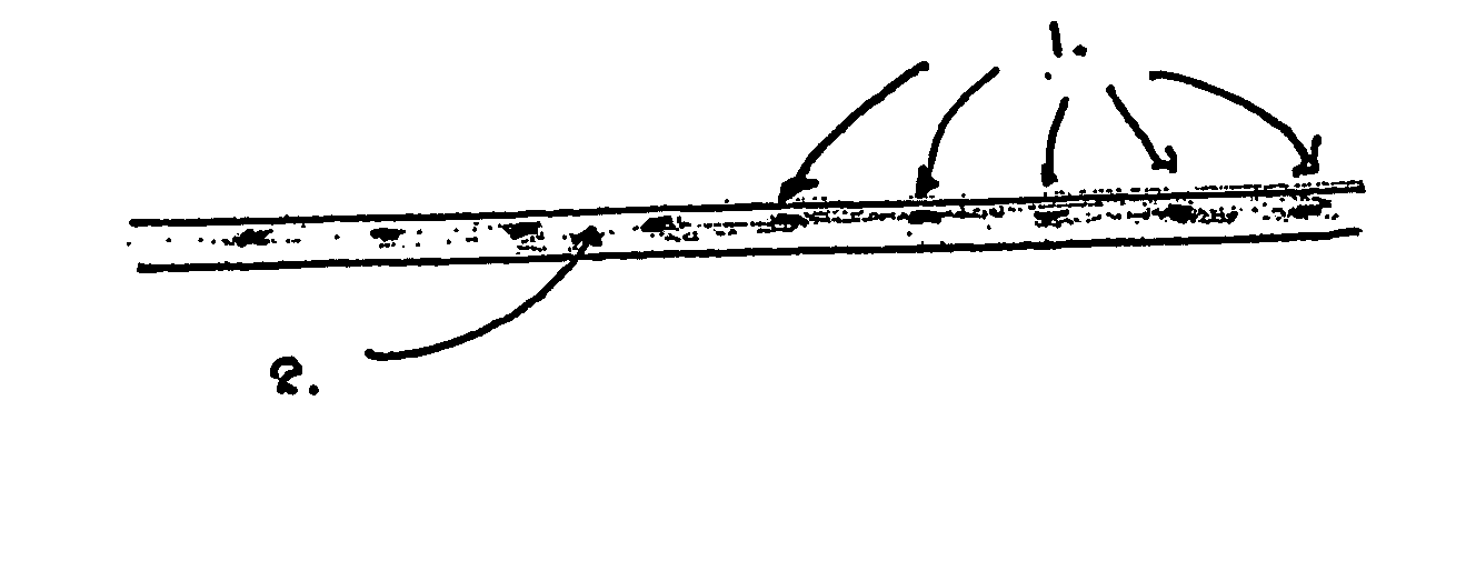
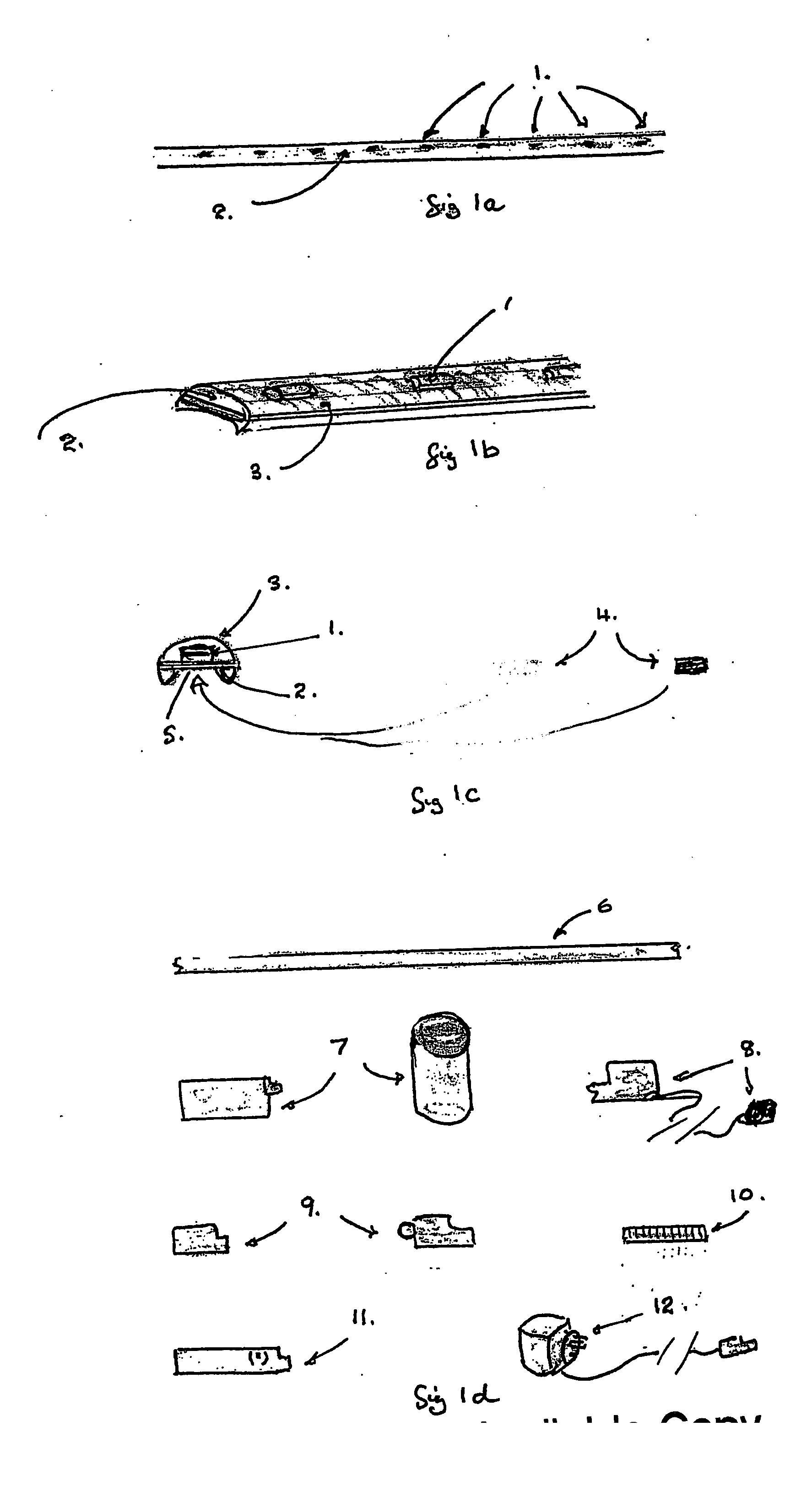
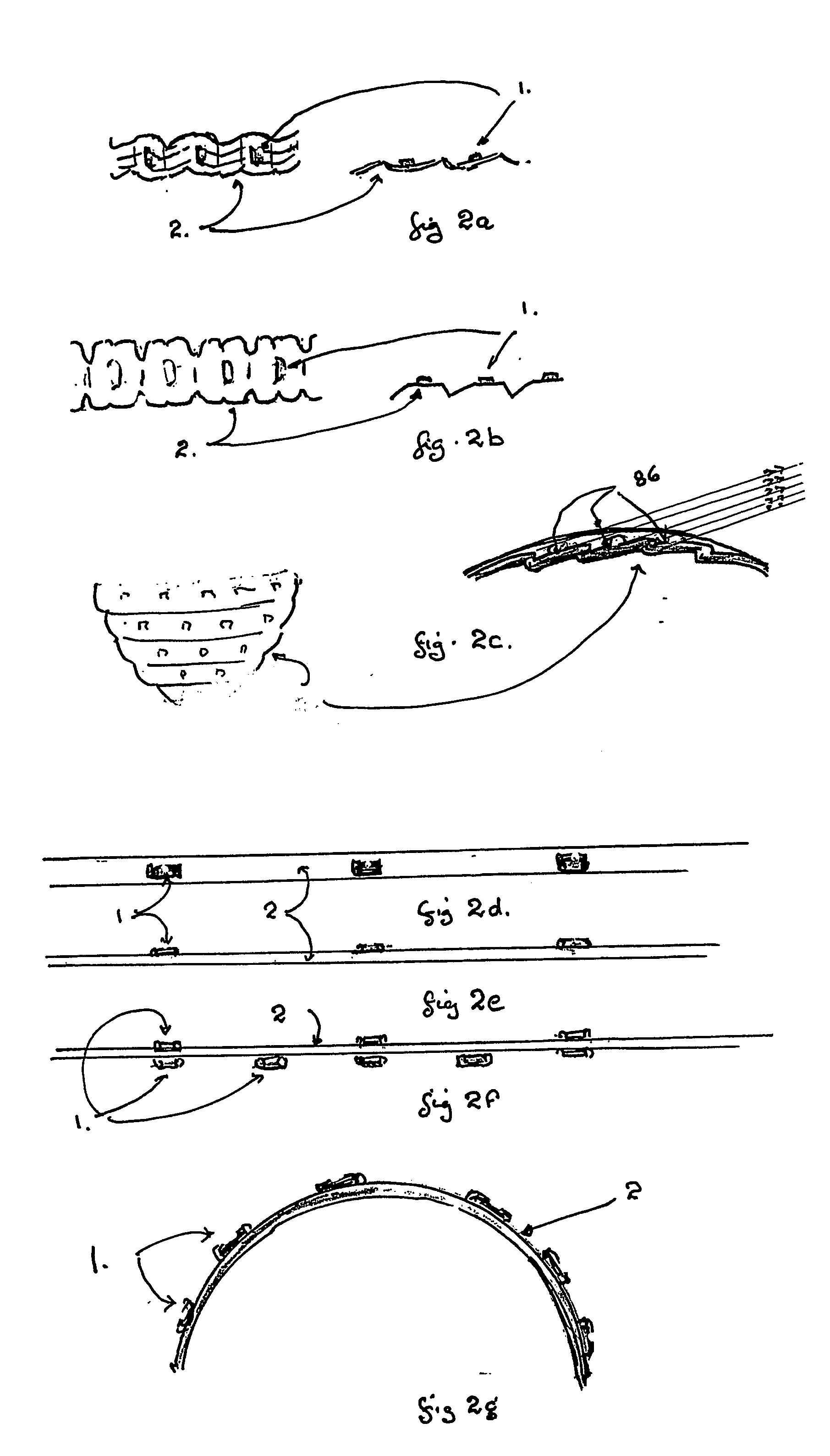
[0038]1 Surface Mounted (SMD) high performance LED's [0039]2 Flexible PCB board mounting selected electronic control components. Maybe pressed, cut, folded, treated, laminated or any combination to improve flexibility. [0040]3 Protective but flexible outer cover, clear, coloured, or with internal coatings. Maybe finished to diffuse, direct, colour, fluoresce or otherwise alter the LED's light [0041]4 Possible mounting methods: Magnetic tape, Velcro, double sided tape, Adhesive backing, clip or hook or other means [0042]5 Possible base profile of cover (3) to allow invisible mounting [0043]6 Basic lineal component of LIGHTFINGER, consists of [0044] (1) LED's [0045] (2) PCB with electric components to suit application [0046] (3) Cover [0047]7 End caps containing rechargeable battery or connections for hard wiri...


PUM


Abstract

A visual recognition and identification apparatus comprising a mounting means (2, 18) adapted for placement in a physical environment wherein the mounting means incorporates one or a plurality of light emitting diodes (1) adapted to provide a visual signal characterised in the light emitting diodes (1) are mounted and physically associated with the printed circuit circuit board (2, 18) wherein the printed circuit board (2, 18) has been modified to provide a distinct angle mounting for the light emitting diodes (1) to provide a defined viewing angle and wherein the printed circuit board (2, 18) is manufactured from the compliant material so as to allow the visual recognition and identification apparatus to be moulded and adapted to a number of environments including fixture to non flat surfaces, incorporation into clothing (19, 21), caps and badges by way of sewing or incorporation into a range of devices.

Description

[0001] This invention relates to the methods and apparatus to visually improve the recognition of individuals, equipment, and define, or identify areas of potential physical danger in poor and very low levels of light. BACKGROUND OF THE INVENTION [0002] There exists a need to assist with the visual identification of people and objects in low levels of ambient light. Emergency workers are often required to work in dangerous conditions where there is no available general light (including sunlight) or extremely low levels of illumination. The current safety methods used to identify people; equipment or hazards rely heavily on the use of reflective materials combined within either their safety clothing or reflective signs, barriers or other light reflective materials. All these items require the application of a light source such as a torch or spotlight beam reflecting light off these special surfaces back to the eyes of an observer. [0003] Portable emergency high performance floodlight...

Claims


Application Information

Patent Timeline
IPC IPC(8): A01K11/00A01K27/00A41D13/01A42B1/24A44C3/00B60Q1/32B60Q1/50B60Q1/52B60Q1/56B60Q7/00E01F9/524E01F9/559E01F9/582F21S4/26F21Y115/10G09F9/302G09F13/22G09F19/22G09F21/02G09F23/04H01L27/15H05K1/18
CPCA01K11/00H05K1/189A41D13/01A42B1/248B60Q1/32B60Q1/323B60Q1/503B60Q1/52B60Q1/56B60Q7/00E01F9/044E01F9/065E01F9/085F21S4/007F21V33/0008F21Y2101/02G09F19/22G09F21/02A01K27/006F21S4/26E01F9/582E01F9/524E01F9/559F21Y2115/10B60Q1/324B60Q1/5035
Inventor TRAYNOR, NEIL
Owner TRAYNOR NEIL
Why Eureka
Try Eureka