

Planar speaker
a planar speaker and acoustic transducer technology, applied in the direction of transducer details, plane diaphragms, fibre diaphragms, etc., can solve the problems of low degree of freedom in the design of the planer acoustic transducer shape or coil impedance, noise generation, and formation methods involved problems, so as to achieve low impedance variation, high sound pressure, and low impedance variation
- Summary
- Abstract
- Description
- Claims
- Application Information
AI Technical Summary
Benefits of technology
Problems solved by technology
Method used
Image

Examples
first embodiment
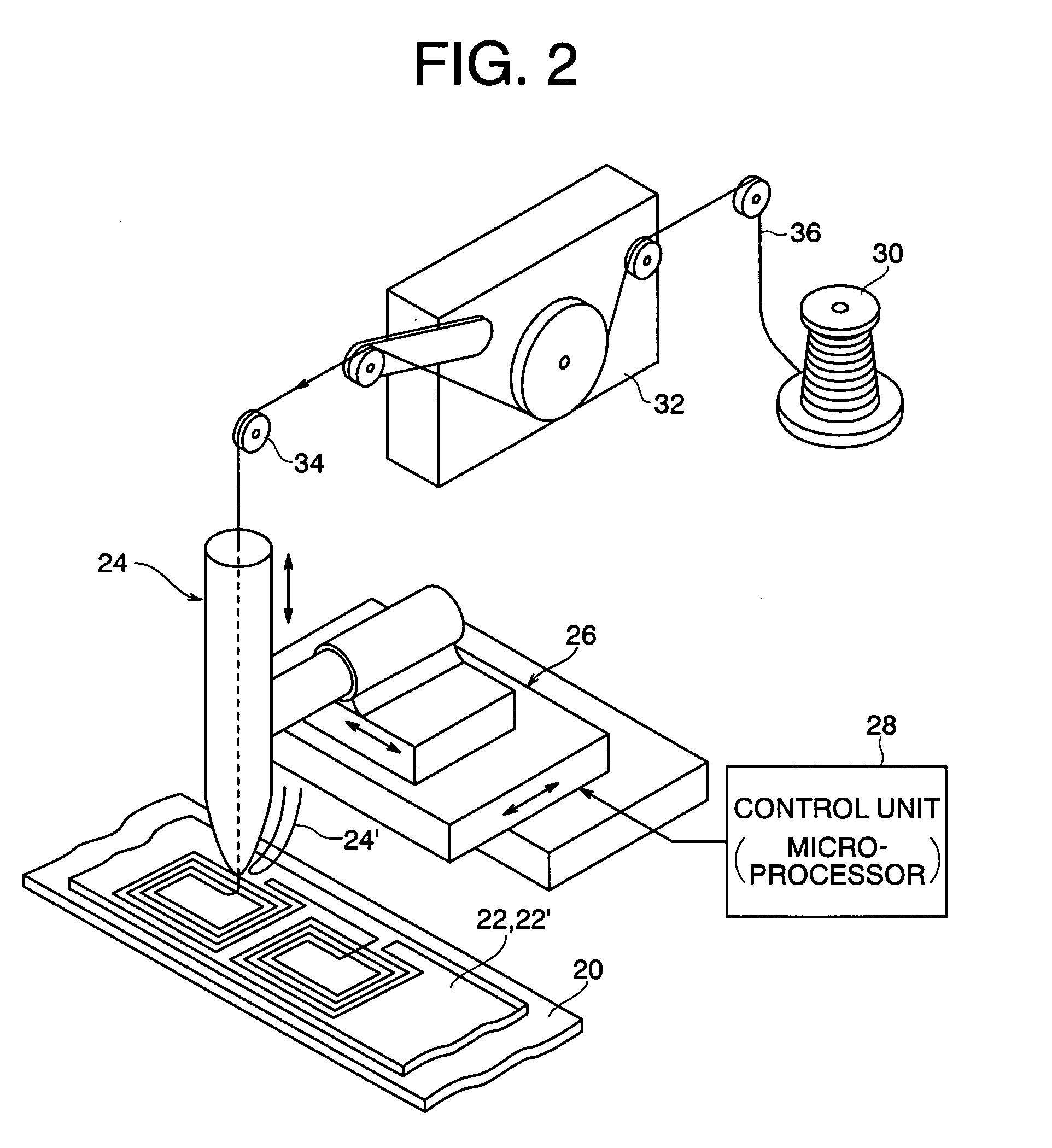
[0087] The wiring apparatus and the wiring method employed in the first invention will now be briefly described with reference to accompanying drawings. As shown in FIG. 2, the wiring apparatus includes a table (conveyer mechanism) 20 on which an adhesive sheet 22 is placed such that its adhesive surface faces upward, and a wiring head 24 which is supported by a moving mechanism (XY table) 26 such that the wiring head can move two-dimensionally with respect to the adhesive sheet. Under control by a control unit 28 including a microprocessor, etc., the moving mechanism 26 causes the wiring head 24 to move two-dimensionally along the surface (adhesive surface) of the adhesive sheet 22, while depicting a predetermined wiring pattern. The wiring head 24 moves vertically in relation to the two-dimensional movement, such that the tip of a nozzle of the wiring head intermittently comes into point contact with the surface of the adhesive sheet 22, whereby a wire conductor 36, which is fed f...
second embodiment
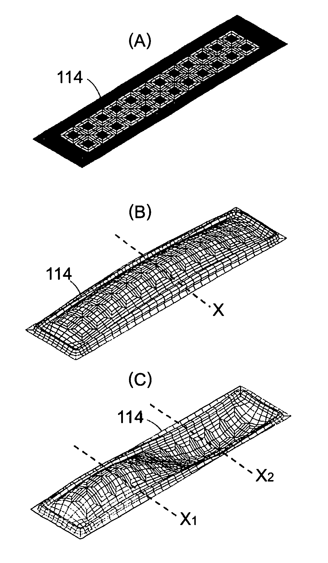
[0100]FIG. 11 shows an embodiment of the second invention. FIG. 11 shows merely a vibrating diaphragm 114, and other components constituting the planer acoustic transducer are similar to those of a conventional planer acoustic transducer (the same shall apply in the below-described embodiments). The vibrating diaphragm 114 includes an insulating base film 116, voice coils 118 (2×4 coils) formed on both surfaces or on one surface of the base film, and rhombic, island-like patterns 138 provided on portions of the base film that correspond to the loops of the first and second vibration modes, the patterns serving as a rigidity-imparting member. In FIG. 11, y1 denotes a ridgeline which passes along the loop of the first vibration mode, and y2 denotes a ridgeline which passes along the loop of the second vibration mode.
[0101] In the case where the voice coils 118 are formed through etching of a metallic foil applied onto the insulating base film 116; i.e., the voice coils are formed by ...
third embodiment
[0103] FIGS. 12(A) and 12(B) show another embodiment of the second invention. In this embodiment, a rib 140 serving as a rigidity-imparting member is attached onto a vibrating diaphragm 114. The rib 140 is attached so as to pass through at least a portion of the vibrating diaphragm 114 that corresponds to the loop of the first or second vibration mode. Preferably, the rib 140 is formed of a material having light weight and exhibiting higher rigidity than that of the insulating base film 116, such as paper, resin, resin foam, metal, wood, thermosetting-resin-impregnated non-woven fabric, or porous ceramic.
[0104] The third embodiment can be applied to the case where the voice coil is formed by means of the subtractive method or the additive method, as well as the case where the voice coil is formed of a metallic thin wire coated with an insulating layer.
PUM
 Abstract
Description
Claims
Application Information