Sound producing device and method for manufacturing same

A technology of a sounding device and a manufacturing method, which is applied in the direction of manufacturing tools, laser welding equipment, electrical components, etc., which can solve the problems of small receivers, difficulty in controlling the welding position, and damage to the welding position, so as to reduce the change of impedance and reduce the sound The effect of pulling and suppressing the fluctuation of the magnetic gap

Inactive Publication Date: 2019-06-14
ALPS ALPINE CO LTD
View PDF8 Cites 1 Cited by
  • Summary
  • Abstract
  • Description
  • Claims
  • Application Information

AI Technical Summary

Problems solved by technology

[0003] In Patent Document 1, it is explained that the armature and the magnetic stack are fixed by resistance welding in the past, and it is pointed out that resistance welding is easy to cause damage to the welding position, and in addition, it is difficult to control the welding position due to the small size of the receiver

Method used


Image

  • Sound producing device and method for manufacturing same
  • Sound producing device and method for manufacturing same
  • Sound producing device and method for manufacturing same

Examples


no. 1 example

[0089] like Figure 7 As shown, in the sounding device 1 as the first embodiment, the fixing portion 32a of the armature 32 and the outer surface 21b of the first yoke 21 are connected by two reference welding portions 51, 51 and two additional welding portions 52, 51 at two positions. 52 to fix the device. The welding part has a total of four positions.

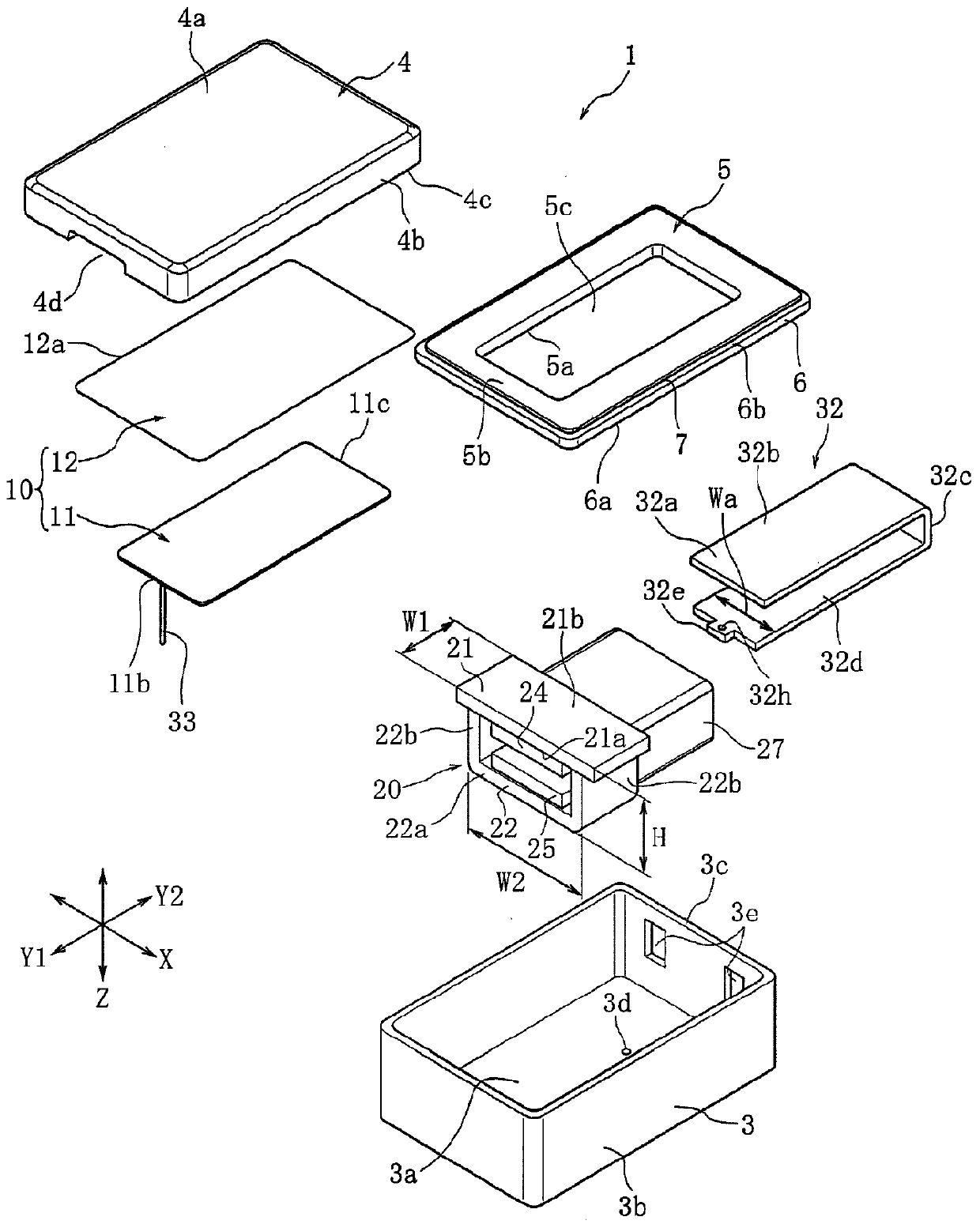
[0090] The plate thicknesses of the first yoke 21 and the second yoke 22 are set to 0.35 mm, and the figure 2The width dimension W1 in the Y direction of the yokes 21 and 22 shown is 1.6 mm, the width dimension W2 in the X direction of the second yoke 22 is 2.7 mm, and the height dimension H in the Z direction of the magnetic field generating unit 20 Set to 1.8mm. As the first magnet 24 and the second magnet, AlNiCo magnets were used. The number of windings of the coil 27 was 200 turns.

[0091] The armature 32 is a PB permalloy, that is, an Fe—Ni alloy containing 45% by mass of Ni, and a thickness of 0.15 mm, figure...

no. 3 example

[0097] like Figure 9 As shown, the sounding device 1 as the third embodiment is formed by welding the fixing portion 32a of the armature 32 and the outer surface 21b of the first yoke 21 with reference welding portions 51 and 51 at two positions and an additional welding portion 52a at six positions in total. , 52a, 52b, 52b and 52c, 52c fixed device. There are eight welding positions in total.

[0098] Other dimensions and the like are the same as in the first embodiment.

[0099] (4) Comparative example

[0100] like Figure 10 As shown, a device in which the fixing portion 32a of the armature 32 and the outer surface 21b of the first yoke 21 are fixed by only two welding portions 53 and 53 is used as a comparative example. The welded portions 53 and 53 are formed at the center position of the first yoke 21 in the Y direction.

[0101] Other dimensions and the like are the same as in the first embodiment.

[0102] (5) Impedance and noise variation

[0103] Figure 1...


PUM


Abstract

According to the present invention, an armature 32 has a fixed part 32a, an extending part 32b, a bent part 32c, and a movable part 32d. The moveable part 32d of the armature 32 is inserted into a coil 27 to face magnets 24, 25, and the fixed part 32a overlaps an outer surface 21b of a yoke 21. Two edge parts 32f, 32f of the fixed part 32a and the outer surface 21b of the yoke 21 are subjected tolaser spot welding to form welded parts 51, 51, 52, 52 in four locations.

Description

technical field [0001] The present invention relates to a sound generating device having a structure in which a fixing portion on the base side of an armature is fixed to an outer surface of a yoke that supports a magnet. Background technique [0002] Patent Document 1 describes an invention related to a receiver as a sound generator and a method of manufacturing the same. [0003] In Patent Document 1, it is described that the armature and the magnetic stack are conventionally fixed by resistance welding, and it is pointed out that the resistance welding easily causes damage to the welding position, and that it is difficult to control the welding position due to the small size of such a receiver. [0004] Therefore, in the invention described in Patent Document 1, the two edge portions of the end portion of the armature and the magnetic stack are welded at two positions by laser welding. In Patent Document 1, according to this method, since the welding position is limited ...

Claims


Application Information

Patent Timeline
Patent Type & Authority Applications(China)
IPC IPC(8): H04R11/02H04R31/00
CPCB23K26/0604B23K26/22B23K26/32B23K2101/36B23K2103/26H04R11/02H04R31/00H04R9/02
Inventor 佐藤清沼田大志青木大悟佐藤丰
Owner ALPS ALPINE CO LTD
Why Eureka
Try Eureka