
A single-excitation two-dimensional ultrasonic vibration-assisted microfabrication platform

A two-dimensional ultrasonic vibration and micromachining technology, which is applied in the direction of fluid using vibration, can solve the problems of small ultrasonic amplitude and affect the machining accuracy of the machine tool spindle, reduce energy loss, realize two-dimensional ultrasonic vibration auxiliary processing, high The Effect of Precision Ultrasonic Ellipse Machining

Active Publication Date: 2019-09-27
NORTHEASTERN UNIV LIAONING
View PDF5 Cites 0 Cited by
  • Summary
  • Abstract
  • Description
  • Claims
  • Application Information

AI Technical Summary

Problems solved by technology

[0003] At present, the research on ultrasonic vibration-assisted milling and grinding is mainly based on the one-dimensional ultrasonic vibration of the spindle. This method requires a large change to the spindle, which affects the inherent high machining accuracy of the machine tool spindle, and the ultrasonic amplitude generated is relatively small. Small
The research on 2D ultrasonic vibration assisted machining is still in the exploratory stage, and there are still many technical problems to be solved in applying 2D ultrasonic vibration to the spindle.

Method used


Image

  • A single-excitation two-dimensional ultrasonic vibration-assisted microfabrication platform
  • A single-excitation two-dimensional ultrasonic vibration-assisted microfabrication platform
  • A single-excitation two-dimensional ultrasonic vibration-assisted microfabrication platform

Examples


Embodiment Construction

[0017] The preferred embodiments of the present invention will be described in detail below in conjunction with the accompanying drawings, so that the advantages and features of the present invention can be more easily understood by those skilled in the art, so as to define the protection scope of the present invention more clearly.

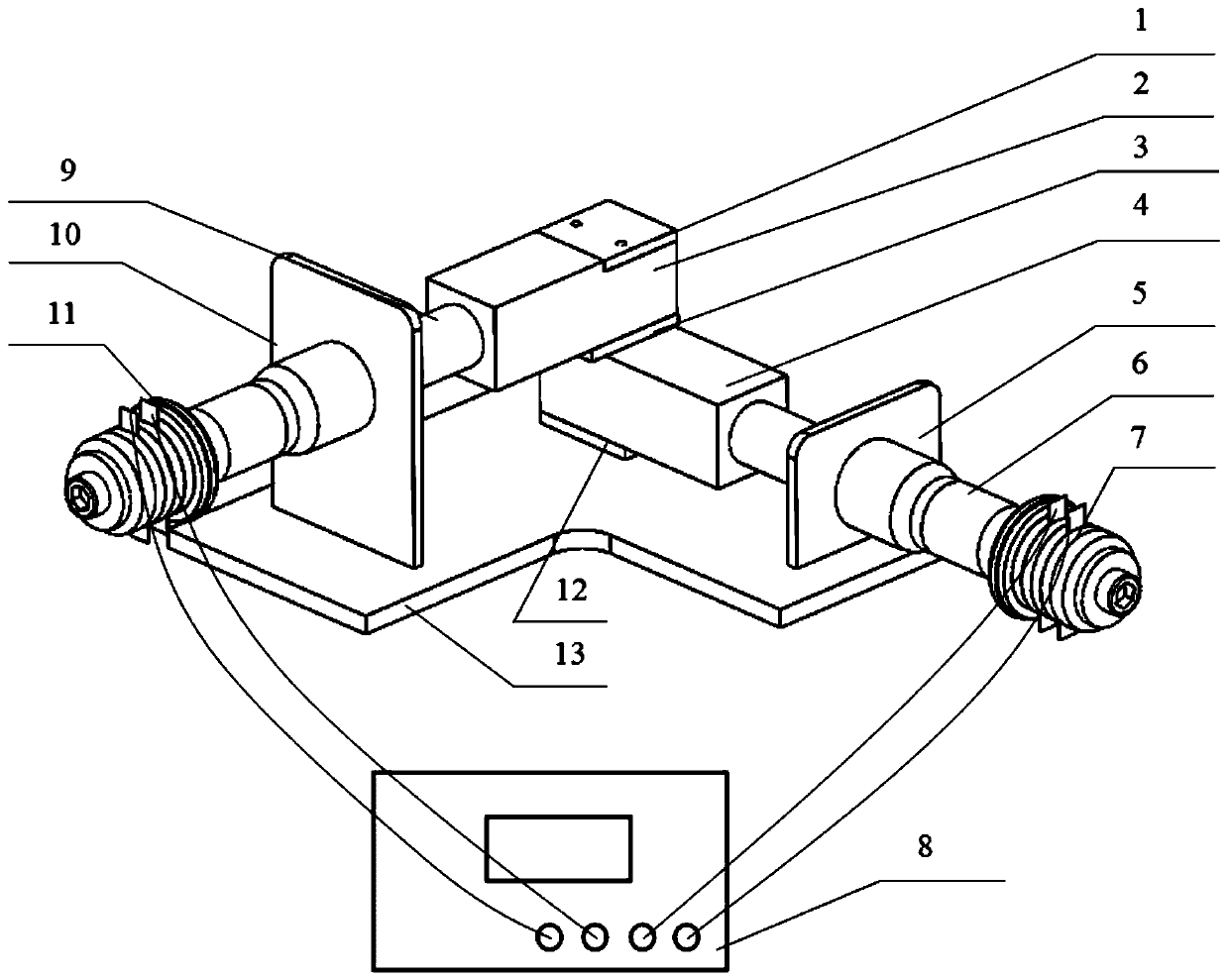
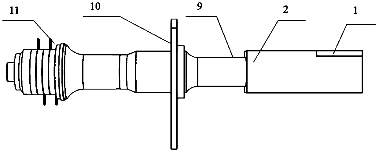
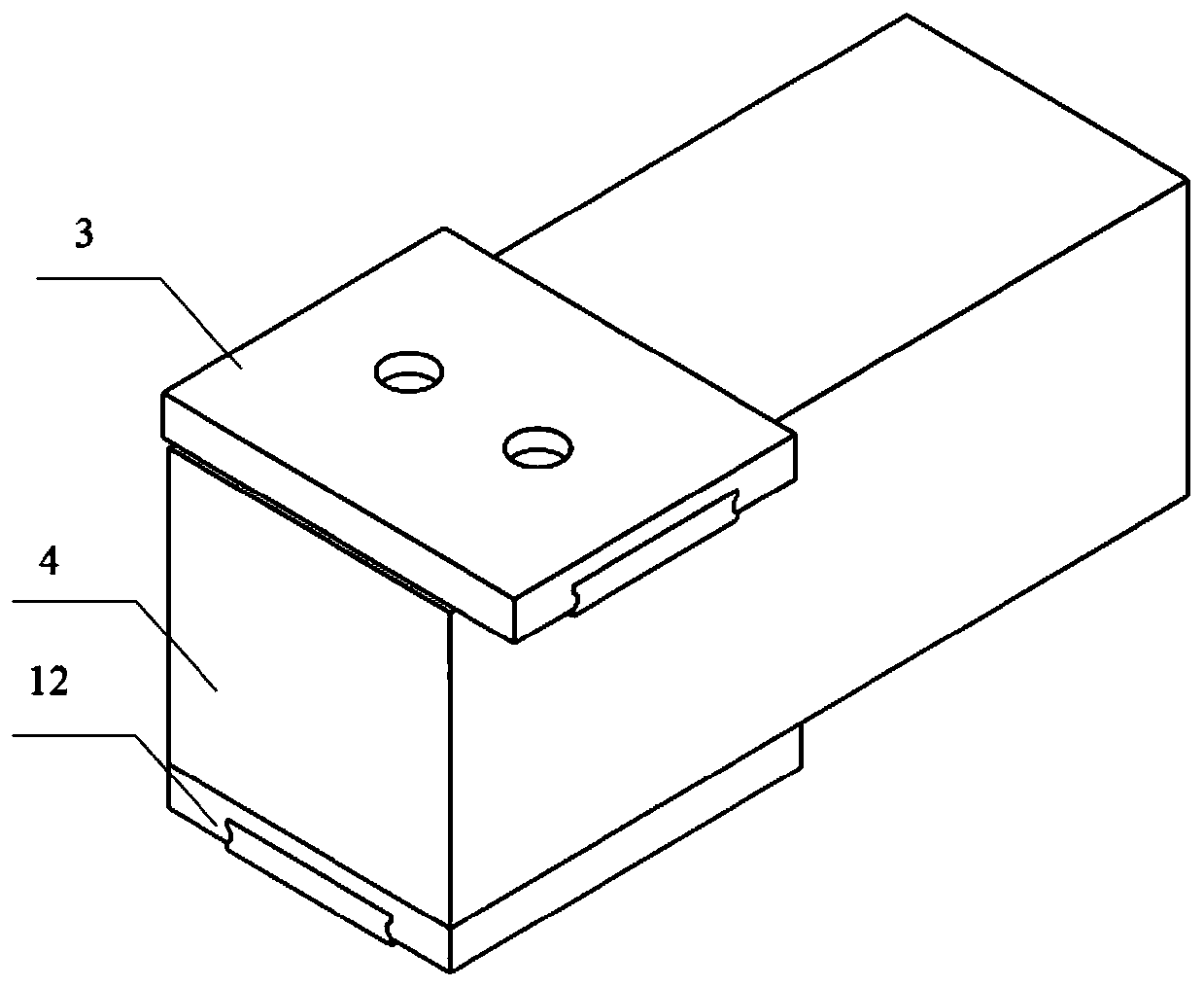
[0018] A single-excitation two-dimensional ultrasonic vibration-assisted microfabrication platform, such as figure 1 , figure 2 and image 3 As shown, the embodiment of the present invention includes: a right-angled bottom plate 13, an upper vibrating mass 2 and a lower vibrating mass 4 optimized according to the resonance frequency and formation, a linear guide rail A3 and a linear guide rail B12, a long support plate 10, a short support plate 5, Horn B6 and horn A9, transducer B7 and transducer A11, ultrasonic generator 8. The right-angled bottom plate is fixed on the machine table, the upper vibrating block 2 and the lower vibrating block 4...


PUM


Abstract

The invention belongs to the technical field of ultrasonic machining of non-traditional machining technologies and discloses a single-excitation two-dimensional ultrasonic vibration-assisted micro machining platform. The single-excitation two-dimensional ultrasonic vibration-assisted micro machining platform comprises a right-angle-shaped bottom plate, linear guide rails, an upper vibration block, a lower vibration block, supporting plates, amplitude-change poles, transducers and an ultrasonic generator. The upper vibration block and the lower vibration block are perpendicular to each other in the feeding and cutting edge working engagement directions. The lower vibration block is connected with the bottom plate through the corresponding linear guide rail, and the lower vibration block is connected with the upper vibration block through the corresponding linear guide rail. A workpiece is fixed to the upper vibration block in a threaded connection mode. The vibration blocks are connected with the amplitude-change poles through studs, and the amplitude-change poles are connected with the transducers through studs. The two amplitude-change poles are fixed to the bottom plate through the supporting plates at joints. The two transducers are connected with the same ultrasonic generator through guide lines, two ultrasonic signals are output simultaneously, the phase difference adjusting function is achieved, by adjusting the amplitude and phase difference of the output signals of the ultrasonic generator, different elliptical vibration paths are coupled according to actual demands, and high-efficiency and high-precision machining is achieved.

Description

technical field [0001] The invention belongs to the technical field of ultrasonic processing in special processing technology, relates to the field of micromachining assisted by two-dimensional ultrasonic vibration, and particularly relates to a single-excitation two-dimensional ultrasonic vibration assisted micromachining platform. Background technique [0002] In recent years, ultrasonic machining has been proven to be a special processing method with strong technological advantages, which can effectively reduce cutting force and cutting heat, improve workpiece surface quality and chip formation, and improve machining accuracy, tool durability and machining stability. It can well solve the processing problems of difficult-to-machine materials, non-metal materials, and parts with high surface quality requirements. As an emerging special processing technology, it has attracted extensive attention from domestic and foreign experts and scholars. [0003] At present, the resear...

Claims


Application Information

Patent Timeline
Patent Type & Authority Patents(China)
IPC IPC(8): B06B1/10B23D79/00
Inventor 倪陈兵朱立达刘长福敦艺超王润琼杨志超
Owner NORTHEASTERN UNIV LIAONING
Learn More