Tendon-driven endoscope and methods of insertion

a technology applied in the field of tendons and endoscopes, can solve the problems of complicated insertion of the colonoscope, and increased complications, and achieve the effect of preventing unintended tension on the tendons

Inactive Publication Date: 2005-07-14
INTUITIVE SURGICAL
View PDF99 Cites 76 Cited by
  • Summary
  • Abstract
  • Description
  • Claims
  • Application Information

AI Technical Summary

Benefits of technology

[0014] Another variation of the endoscope uses ring-shaped support pieces, or vertebrae, as control rings to achieve bendable segments. A segment is comprised of a plurality of adjacent or stacked vertebrae where the vertebrae are connected to each other by jointed sections, e.g., hinged joints, giving the segment flexibility in any direction. Thus, vertebra-type control rings can be hinged to adjacent vertebrae by flanges with through holes. In one variation, pairs of hinge joints project perpendicularly from the face of each vertebra and can connect to the hinge joints of adjacent vertebrae both proximally and distally. Each pair of hinge joints allows limited motion in one axis. The hinge joints projecting from the opposite face of the vertebra are preferably located 90 degrees in rotation from the pair on the other face of the vertebra. This creates a second axis of motion in a plane perpendicular to the first. Adding additional vertebrae in this way result in a segment that could be bent in any direction. For example, approximately ten vertebrae could be linked to create one such segment. Other variations can have more or fewer vertebrae per segment.
[0015] In addition to hinged joints; there are other features that could be included in the control ring. Thus, the inner surface of the vertebra could have channels forming a common lumen in the endoscope, such as for the working channels, the air and water channels, the optical fiber channels, tendons, and so forth. The vertebra could also include attachment sites for the tendons, including the sleeve and inner cable of the Bowden cable embodiments. Further, the outer edge of the control ring could include channels for holding tendons that control more distal segments. These channels could provide methods of arranging and organizing such tendons. For example, in another variation, the tendons controlling more distal segments are helically wound around the outer surface of more proximal segments as the tendons project proximally to the controller. Such helical winding could prevent unintended tension on tendons controlling more distal segments when proximal segments are bent. Alternatively, the tendons can include excess “slack.” Such excess slack could also help prevent proximal segments from being constrained by bypassing tendons controlling more distal segments.
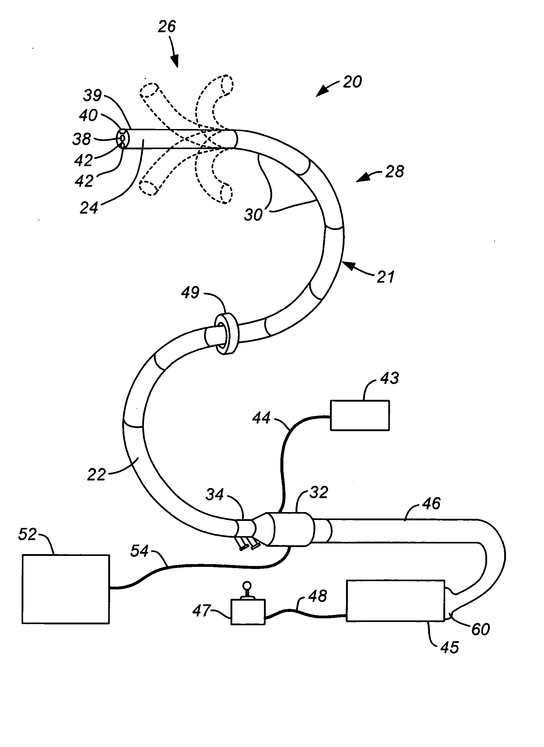
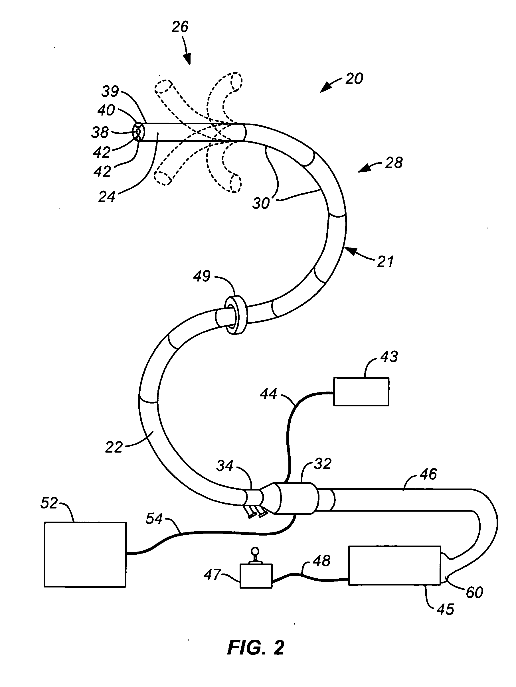
[0021] Similarly, it is desirable that the endoscope be easily disconnected from the controller. The tendons projecting proximally from the segments of the endoscope are collectable in a umbilicus that has an interface which couples with a controller unit containing the actuators, e.g., motors, that apply force to the tendons. This interface may be a quick-disconnect mechanism between the tendons and the controller. One variation of the quick-disconnect mechanism is a “nail head” positionable in a slot design in which the terminus of each tendon cable is configured into, e.g., a flattened protrusion. An array of such tendons at the end of the umbilicus mates with an interface on the controller. The flattened tendon ends may be fitted into corresponding slots defined in the controller housing. The corresponding fit enables the tendon ends to be removably secured within their respective slots and thereby allows the actuators to apply force to specific tendons. Further, the controller can determine the shape of a segment based on the tension being applied by its controlling tendons. The controller can also be adapted to determine segment configuration based upon the position of the cable relative to the cable housing. Moreover, the controller may be further adapted to sense the amount of rotation or linear movement of the controlling tendons and can determine segment configuration based upon this data.
[0023] A typical endoscope has a diameter less than 20 mm, although various industrial applications may utilize endoscopes having a diameter greater than 20 mm. Likewise, one variation of this invention also has a radial dimension of less than 20 mm. In another variation of the invention, the radius of more distal segments decreases in a telescope-like fashion. This allows the steerable distal portion to have a much smaller radius, e.g., 12.5 mm, than the more proximal segments. In this variation, the larger radius of more proximal segments provides increased space for tendons from distal segments.

Problems solved by technology

Insertion of the colonoscope is complicated by the fact that the colon represents a tortuous and convoluted path.
Considerable manipulation of the colonoscope is often necessary to advance the colonoscope through the colon, making the procedure more difficult and time consuming and adding to the potential for complications, such as intestinal perforation.
However, as the colonoscope is inserted farther into the colon, it becomes more difficult to advance the colonoscope along the selected path.
Friction and slack in the colonoscope build up at each turn, making it more and more difficult to advance and withdraw, and can result in looping of the colonoscope.
In addition, the force against the wall of the colon increases with the buildup of friction.
In cases of extreme tortuosity, it may become impossible to advance the colonoscope all of the way through the colon.

Method used


Image

  • Tendon-driven endoscope and methods of insertion
  • Tendon-driven endoscope and methods of insertion
  • Tendon-driven endoscope and methods of insertion

Examples


Embodiment Construction

[0046]FIG. 1 shows a prior art colonoscope 10 being employed for a colonoscopic examination of a patient's colon C. The colonoscope 10 has a proximal handle 16 and an elongate body 12 with a steerable distal portion 14. The body 12 of the colonoscope 10 has been lubricated and inserted into the colon C via the patient's anus A. Utilizing the steerable distal portion 14 for guidance, the body 12 of the colonoscope 10 has been maneuvered through several turns in the patient's colon C to the ascending colon G. Typically, this involves a considerable amount of manipulation by pushing, pulling and rotating the colonoscope 10 from the proximal end to advance it through the turns of the colon C. After the steerable distal portion 14 has passed, the walls of the colon C maintains the curve in the flexible body 12 of the colonoscope 10 as it is advanced. Friction develops along the body 12 of the colonoscope 10 as it is inserted, particularly at each turn in the colon C. Because of the frict...


PUM


Abstract

A steerable, tendon-driven endoscope is described herein. The endoscope has an elongated body with a manually or selectively steerable distal portion and an automatically controlled, segmented proximal portion. The steerable distal portion and the segment of the controllable portion are actuated by at least two tendons. As the endoscope is advanced, the user maneuvers the distal portion, and a motion controller actuates tendons in the segmented proximal portion so that the proximal portion assumes the selected curve of the selectively steerable distal portion. By this method the selected curves are propagated along the endoscope body so that the endoscope largely conforms to the pathway selected. When the endoscope is withdrawn proximally, the selected curves can propagate distally along the endoscope body. This allows the endoscope to negotiate tortuous curves along a desired path through or around and between organs within the body.

Description

CROSS-REFERENCE TO RELATED APPLICATIONS [0001] This application is a continuation-in-part of U.S. patent application Ser. No. 09 / 790,204 entitled “Steerable Endoscope and Improved Method of Insertion” filed Feb. 20, 2001, which claims the benefit of priority to U.S. Provisional Patent Application Ser. No. 60 / 194,140 entitled the same and filed Apr. 3, 2000, both of which are incorporated herein by reference in their entirety.FIELD OF THE INVENTION [0002] The present invention relates generally to endoscopes and endoscopic procedures. More particularly, it relates to a method and apparatus to facilitate insertion of a flexible endoscope along a tortuous path, such as for colonoscopic examination and treatment. BACKGROUND OF THE INVENTION [0003] An endoscope is a medical instrument for visualizing the interior of a patient's body. Endoscopes can be used for a variety of different diagnostic and interventional procedures, including colonoscopy, bronchoscopy, thoracoscopy, laparoscopy a...

Claims


Application Information

Patent Timeline
Patent Type & Authority Applications(United States)
IPC IPC(8): A61B1/00G02B23/24A61B1/005A61B1/008A61B1/01A61B1/04A61B1/31G02B23/26
CPCA61B1/0053A61B1/0058A61B1/01A61B1/31A61B1/0057A61B2019/2211A61B2019/2273A61B2019/2276A61B1/00128A61B5/065A61B2034/742A61B2034/301A61B2034/741A61B1/00006A61B1/00057A61B1/0016
Inventor OHLINE, ROBERT M.TARTAGLIA, JOSEPH M.BELSON, AMIRROTH, ALEX T.KELLER, WADE A.ANDERSON, SCOTT C.JULIAN, CHRIS A.
Owner INTUITIVE SURGICAL
Why Eureka
Try Eureka