Central toilet/bathroom venting

a toilet and central technology, applied in the direction of lavatory sanitory, water installation, construction, etc., can solve the problem that odors cannot be allowed to fill the room, and achieve the effect of facilitating the attachment of energy recovery systems, facilitating indoor air quality improvement and circulation, and promoting energy efficiency

Inactive Publication Date: 2005-07-21
JOSHUA ZULU
View PDF10 Cites 9 Cited by
  • Summary
  • Abstract
  • Description
  • Claims
  • Application Information

AI Technical Summary

Benefits of technology

[0012] This invention will also facilitate attachment of energy recovery systems in which the exhausted interior air is channeled through a heat exchanger where the energy from the exhausted air is recovered by the incoming air from outside. The energy exchange also facilitates indoor air quality improvement and circulation. This feature is important because most modern buildings and houses are built more tightly to promote energy efficiency. It is intended to accomplish this by providing a tank with a venting hole at the base of the tank or on the back wall of the tank. It is also the intention of this invention that the means for collecting and channeling the odors out of the tank provide the option of being manufactured integral to the tank or modular assembly of odor collecting and channeling components.
[0013] Odor collecting components will be designed or assembled such that odor-collecting points will tower above the designated tank waterline or level, and above the top of the fill tube. This will prevent the exhaust system from ingesting water. Odor collecting points and components will also be located lower than the top rim of-the tank while leaving enough clearance with the lid or cover to provide free flow of air to the suction or collecting points.
[0014] This invention is intended to vent odors or fumes by providing another hole at the bottom of the tank or on the back of the tank. It is anticipated to locate the vent holes or outlets to the right of the centerline of the toilet assembly. By locating the vents to the right of the centerline of the toilet; this invention provides those skilled in the art of building or remodeling homes and other buildings with a known standard location for routing of the odor collecting lines, conduits or other plumbing based on the planned location of the toilet in the bathroom. Those skilled in the art of building or remodeling homes and other buildings will also be obligated or directed to provide space behind the wall free of internal structural reinforcement to facilitate easy installation of venting lines or conduits during or after completion of construction of the premises. The option of locating the vent hole at the bottom or back of the tank is intended to account for the difference in current and future tank styles without changing the design or profile. While the size of the vent holes may vary depending on the features and shape of the tank it is advised to be the same size as the flush valve installation hole to simplify installation components and tools.

Problems solved by technology

This means that odors will-not be allowed to fill the room before being exhausted.

Method used


Image

  • Central toilet/bathroom venting
  • Central toilet/bathroom venting
  • Central toilet/bathroom venting

Examples


Embodiment Construction

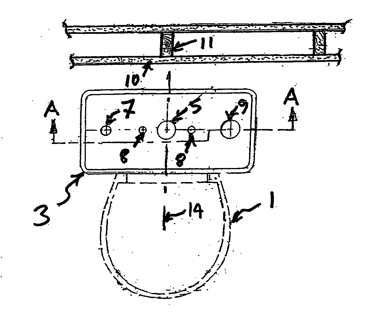
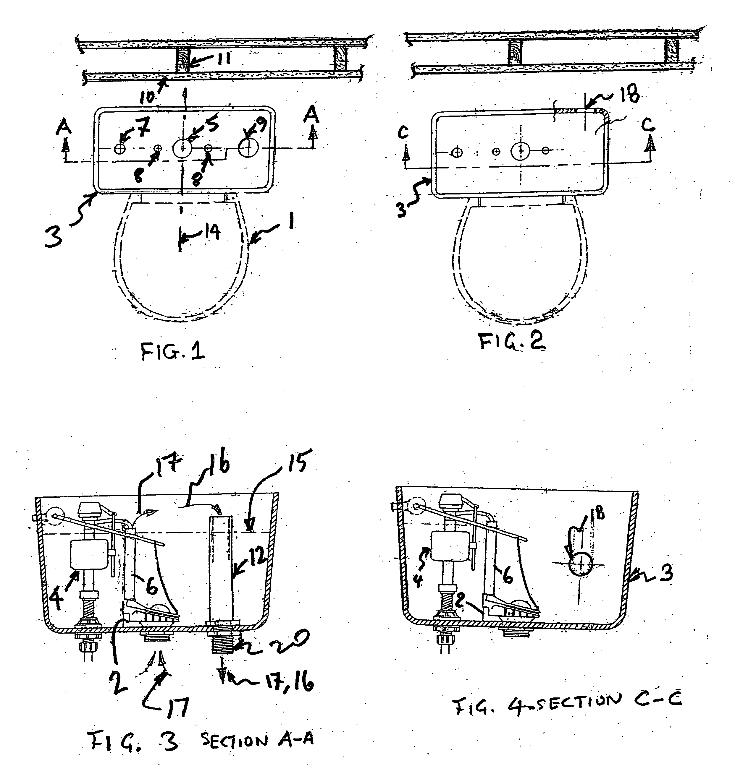
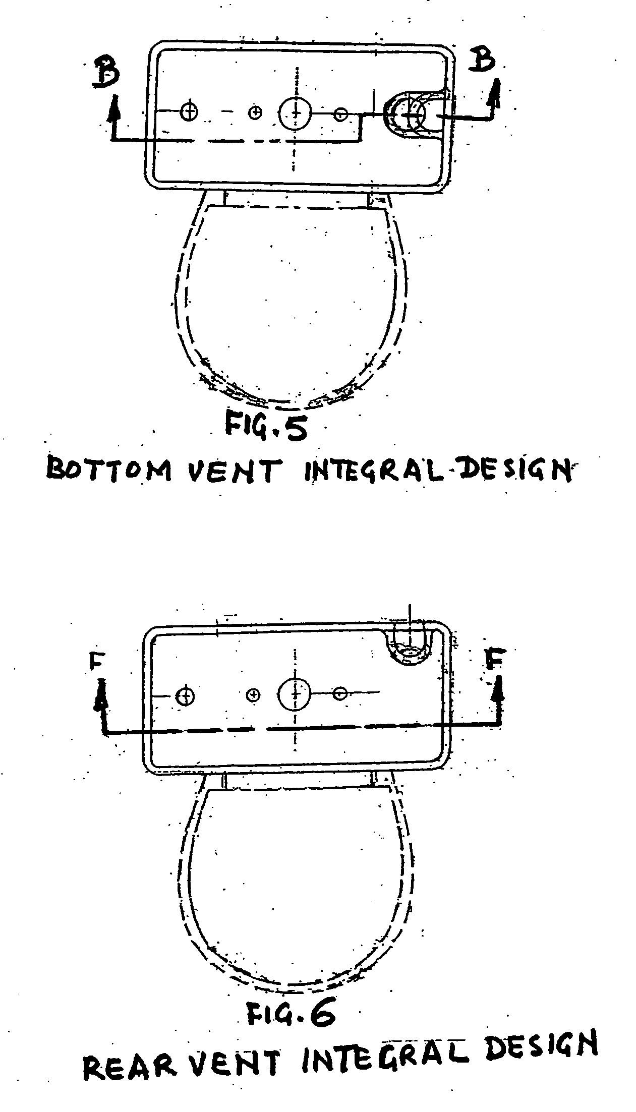
[0029] In accordance with a first embodiment of the present invention, there is provided a venting system as depicted in FIG. 11. The venting system includes toilet assemblies having special features in terms of a venting opening at the bottom of the tank, FIG. 11A and / or a venting opening at the back of the tank as in, FIG. 11B. The venting system also includes branch conduits 23 which are connected to a larger central venting conduit 24. The larger conduit 24 is connected to an electrically driven or powered fan / blower or energy recovery exhaust system 25. The venting system and assembly has a final discharge outlet 26 which is equipped with a back draft prevention damper 27. The purpose of the back draft damper is to prevent reverse flow of what the fan is exhausting through the ducts and conduits when the fan is off.

[0030]FIG. 11 shows one of the most efficient modes for utilizing this invention by connecting appropriate exhaust lines to outlet connectors 20 so that the odors w...


PUM


Abstract

A venting system is disclosed. The system includes an exhaust fan connected to a discharge outlet as well as central and branch conduits for collecting odors or fumes. The system includes an electric power supply and switches for activating and de-activating the exhaust fan.

Description

CROSS-REFERENCE TO RELATED APPLICATIONS [0001] This application claims priority of provisional application No. 60 / 538,045, filed on Jan. 21, 2004.STATEMENT REGARDING FEDERALLY SPONSORED RESEARCH OR DEVELOPMENT [0002] Not Applicable. APPENDIX [0003] Not Applicable. BACKGROUND OF THE INVENTION [0004] 1. Field of the Invention [0005] The present invention relates generally to venting a toilet assembly, and more particularly to venting via the tank or water closet portion of the toilet assembly. [0006] 2. Related Art [0007] A typical toilet assembly is composed of a bowl, tank and lid. The bowl functions as support for a seat assembly on which a typical user sits. In a two-piece assembly the bowl also functions as a support for the tank while in a single piece design the bowl and tank are molded as one piece. The bowl contains passages under the rim for transporting water from the tank into the bowl for flushing waste and cleaning the walls of the bowl. [0008] The tank functions as supp...

Claims


Application Information

Patent Timeline
Patent Type & Authority Applications(United States)
IPC IPC(8): E03D9/05
CPCE03D9/05
Inventor ZULU, JOSHUA
Owner JOSHUA ZULU
Why Eureka
Try Eureka