Fuel injection control device for internal combustion engine

a technology of control device and internal combustion engine, which is applied in the direction of electric control, machines/engines, mechanical equipment, etc., can solve the problem of allowing room for improvement in respons

Inactive Publication Date: 2005-07-21
TOYOTA JIDOSHA KK
View PDF7 Cites 132 Cited by
  • Summary
  • Abstract
  • Description
  • Claims
  • Application Information

AI Technical Summary

Benefits of technology

[0013] The present invention has been made to solve the above-mentioned problem. It is an object of the present invention to provide a fuel injection control device which enables an internal combustion engine to make excellent responses to load changes.

Problems solved by technology

This means that the conventional dual-injector type internal combustion engines leave room for improvement in terms of response to load changes.

Method used


Image

  • Fuel injection control device for internal combustion engine
  • Fuel injection control device for internal combustion engine
  • Fuel injection control device for internal combustion engine

Examples


first embodiment

System Configuration of First Embodiment

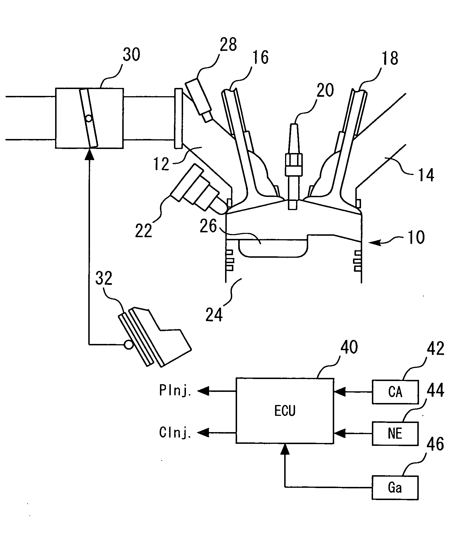
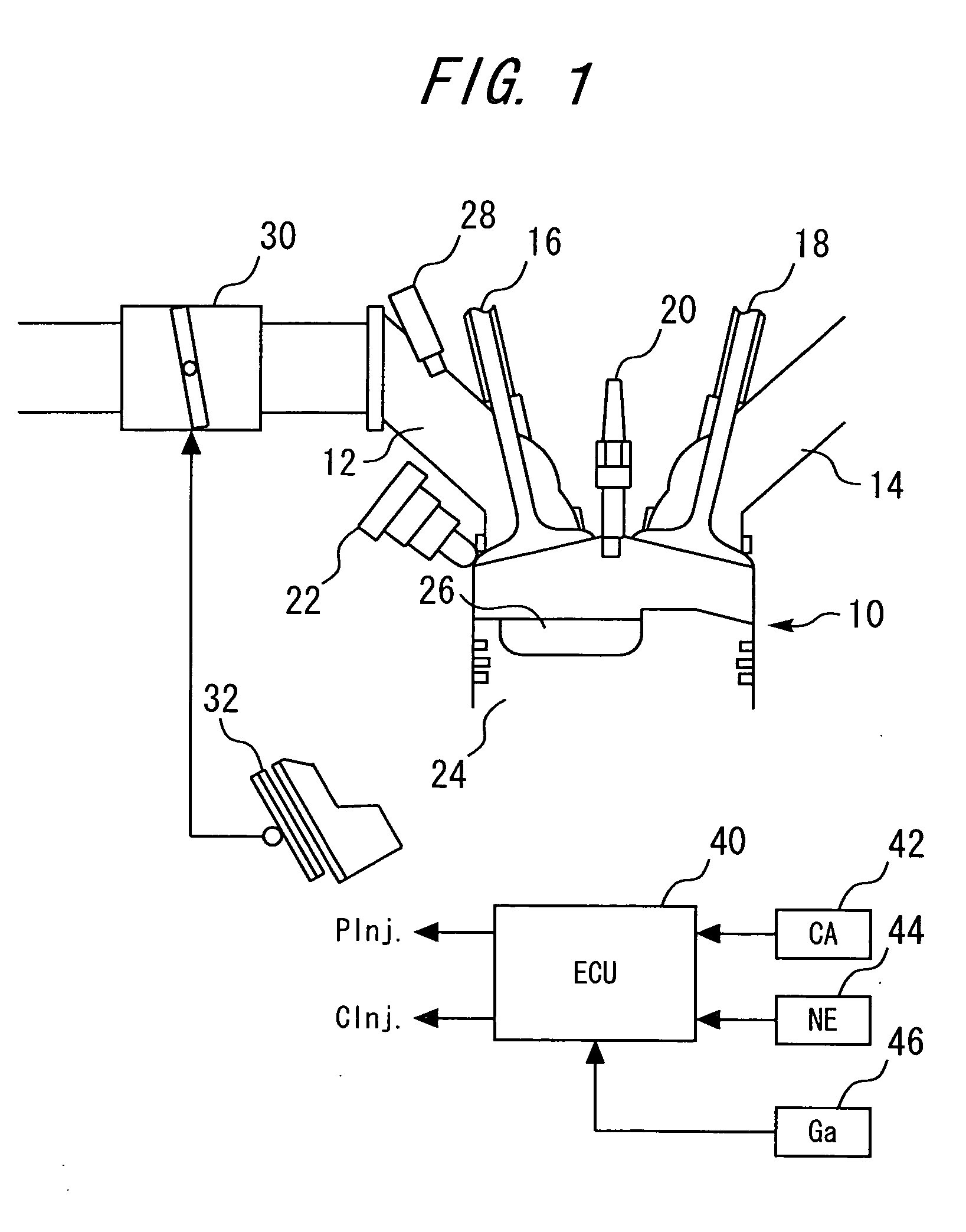
[0022]FIG. 1 is provided to explain the configuration of a first embodiment of the present invention. As shown in FIG. 1, this system embodiment has an internal combustion engine 10. The internal combustion engine 10 is communicated with an intake port 12 and an exhaust port 14. An intake valve 16 is provided between the intake port 12 and the in-cylinder space of the internal combustion engine 10. An exhaust valve 18 is provided between the exhaust port 14 and the in-cylinder space of the internal combustion engine 10.

[0023] In addition, a spark plug 20 and an in-cylinder injector (DInj) 22 for direct injection into the cylinder are set to the internal combustion engine 10. The tip of the spark plug 20 is exposed in the middle of the in-cylinder space. The tip of the in-cylinder injector 22 is directed toward the center of the in-cylinder space. The piston 24 of the internal combustion engine 10 has a cavity 26 formed on its top surface. Fue...

second embodiment

Characteristics of Second Embodiment

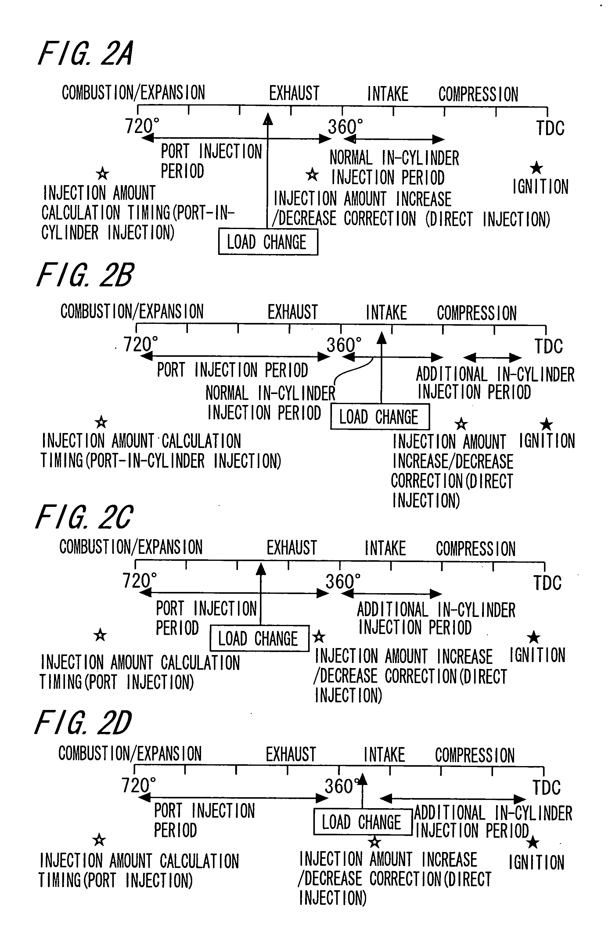
[0072] In the internal combustion engine 10, some transport delay occurs until fuel is introduced into the cylinder after the fuel is injected from the port injector 28. Therefore, increasing or decreasing the port injection fuel amount according to the change of the engine load is not immediately reflected in the amount of fuel to be injected into the cylinder from the intake port 12. Consequently, in a transient period responding to a load increase, the amount of fuel entering the cylinder from the intake port 12 is smaller than the ideal value. Also in a transient period responding to a load decrease, the mount of fuel entering the cylinder from the intake port 12 is larger than the ideal value.

[0073] On the contrary, the fuel injected from the in-cylinder injector 22 is supplied into the cylinder without transport delay. Therefore, when the amount of fuel injected into the cylinder from the intake port 12 is deficient, the in-cylinder injecti...


PUM


Abstract

An internal combustion engine (10) is provided with a port injector (28) and an in-cylinder injector (22). Before a port injection is started, the total amount of fuel to be injected is calculated (at an injection amount calculation timing). The port injection fuel amount and the in-cylinder injection fuel amount are calculated by appropriately dividing the total amount between them. If a change of the operating load on the internal combustion engine (10) is detected after the injection amount calculation timing, the load change is reflected in the amount of fuel to be injected in the current engine cycle by increasing or decreasing the in-cylinder injection fuel amount.

Description

BACKGROUND OF THE INVENTION [0001] 1. Field of the Invention [0002] The present invention relates to a fuel injection control device for an internal combustion engine and, more particularly, to a fuel injection control device for an internal combustion engine which is provided with a port injector to inject fuel into the intake port and an in-cylinder injector to inject fuel into the cylinder. [0003] 2. Background Art [0004] As conventional internal combustion engines, those comprising a port injector to inject fuel into the intake port and an in-cylinder injector to inject fuel into the cylinder are known as disclosed in, for example, Japanese Patent Laid-open No. 2003-13784. In such a prior art internal combustion engine operating under certain conditions, port injection by a port injector is combined with in-cylinder injection by an in-cylinder injector so as to form a fuel-rich layer near the spark plug while introducing uniform mixture into the cylinder. According to this fuel ...

Claims


Application Information

Patent Timeline
Patent Type & Authority Applications(United States)
IPC IPC(8): F02M63/00F02D41/02F02D41/04F02D41/14F02D41/34F02D41/40
CPCF02D41/1498Y02T10/44F02D41/401F02D41/3094F02D41/10Y02T10/40
Inventor ICHISE, MASAHARUKASHIWAGURA, TOSHIMINOGAWA, SHINICHIROHASHIMA, TAKASHI
Owner TOYOTA JIDOSHA KK
Why Eureka
Try Eureka