Coated substrate assembly

a technology of coating and substrate, which is applied in the field of coating assembly, can solve the problems of affecting the use of prior art stents, affecting the effect of stent placement,

Inactive Publication Date: 2005-07-21
BIOPHAN TECH
View PDF99 Cites 72 Cited by
  • Summary
  • Abstract
  • Description
  • Claims
  • Application Information

AI Technical Summary

Benefits of technology

This patent describes a coated assembly that has a high magnetic permeability and a strong magnetization. This makes it useful for applications such as magnetic resonance imaging (MRI) and magnetic resonance spectroscopy (MRS). The coating has a relative magnetic permeability of at least 1.1 and can increase its permeability over a range of frequencies from 10 to 200 megahertz. The magnetization of the coating is measured at a direct current magnetic field of 2 Tesla and is between 0.1 and 10 electromagnetic units per cubic centimeter.

Problems solved by technology

The patent text discusses the difficulty of using magnetic resonance imaging (MRI) with prior art stents because they distort the images. The technical problem is to provide a process that improves the imageability of stents and allows for in situ magnetic resonance imaging of stents, which would allow for the development of a heart valve that could be inserted with patients only slightly sedated, locally anesthetized, and released from the hospital quickly after a procedure.

Method used


Image

  • Coated substrate assembly
  • Coated substrate assembly
  • Coated substrate assembly

Examples


Embodiment Construction

[0063] In the first part of this specification, a preferred seed assembly will be described. Thereafter, other embodiments of the invention will be described.

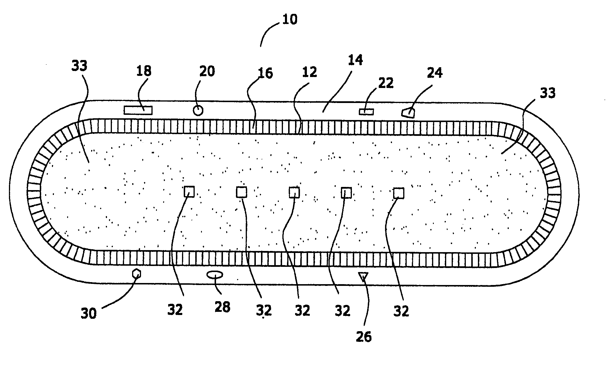
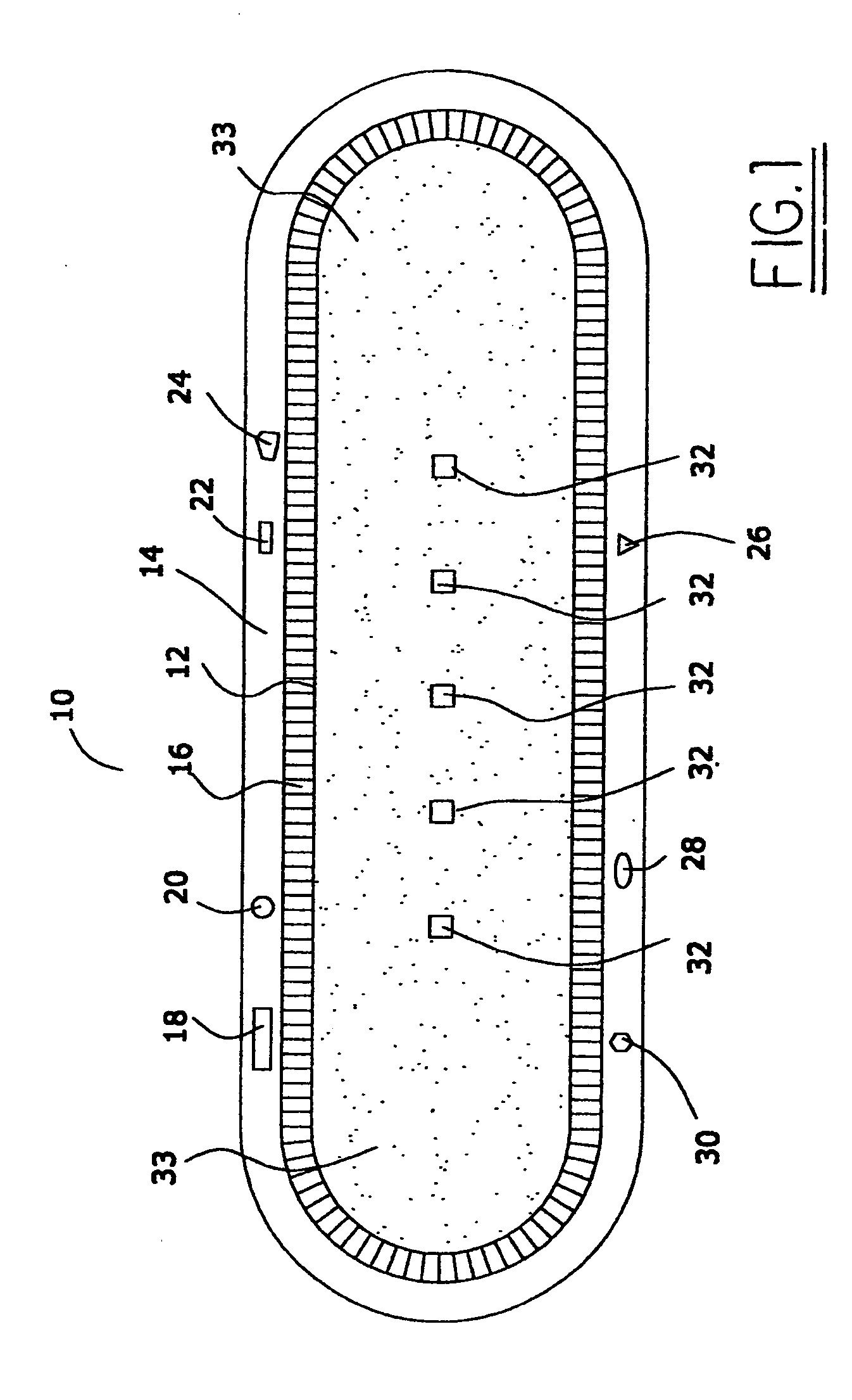
[0064]FIG. 1 is a schematic diagram of a preferred seed assembly 10 of this invention. Referring to FIG. 1, and to the preferred embodiment depicted therein, it will be seen that assembly 10 is comprised of a sealed container 12 comprised of a multiplicity of radioactive particles 33.

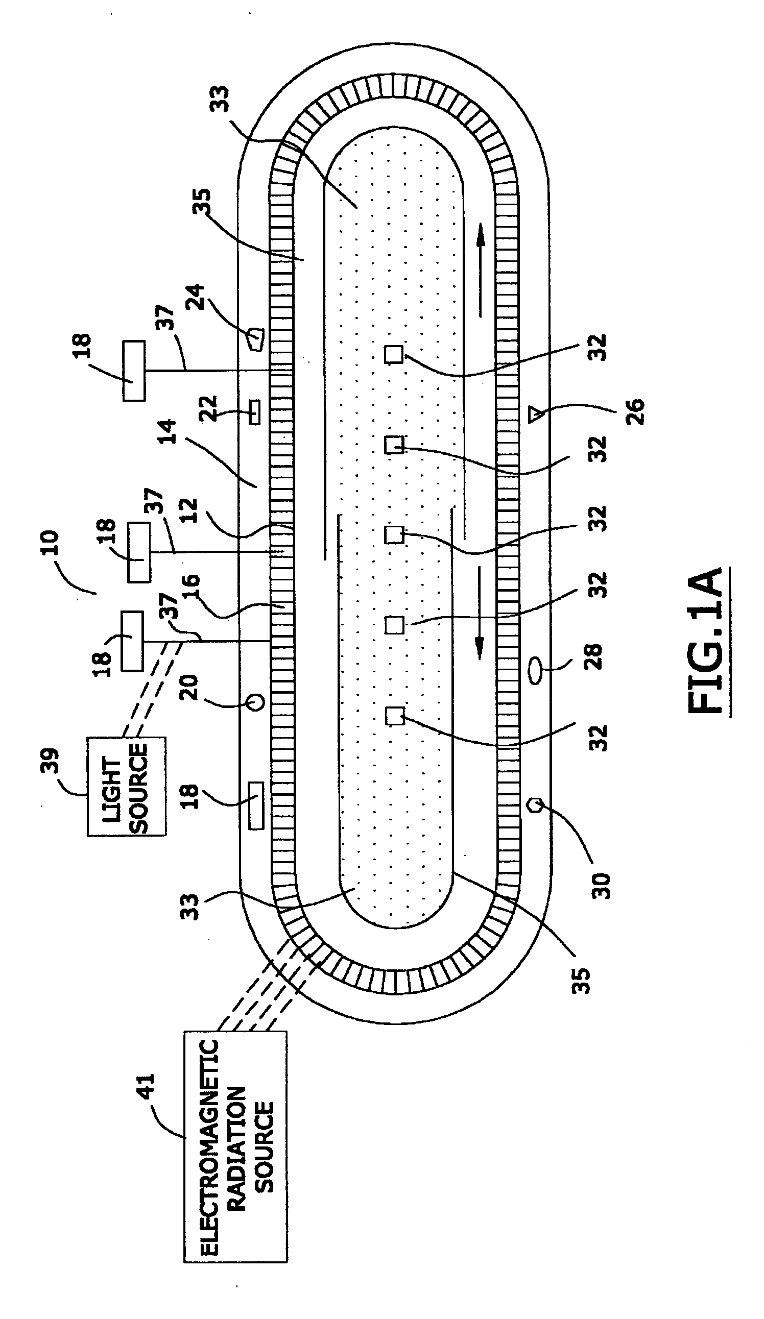
[0065] In one preferred embodiment, and referring to FIG. 1A, the assembly 10 is preferably comprised of a shield 35 that is adapted to prevent radiation from escaping from assembly 10 when such shield is in a first position, and to allow radiation to escape from assembly 10 when such shield is in a second position. It should be recognized that the depiction in FIG. 1A is merely a schematic one that does not necessarily accurately illustrate the size, scale, shape, or functioning of the shield 35.

[0066] One may use prior art radiation shields as...


PUM

PropertyMeasurementUnit
Lengthaaaaaaaaaa
Lengthaaaaaaaaaa
Fractionaaaaaaaaaa

Abstract

A coated assembly comprised of a coating that has a relative magnetic permeability of at least 1.1 over the range of frequencies of from about 10 megahertz to about 200 megahertz, an increase of such relative magnetic permeability over such range of from about 1×10⁻¹⁴ to about 1×10⁻⁶ per hertz, and a magnetization, when measured at a direct current magnetic field of 2 Tesla, of from about 0.1 to about 10 electromagnetic units per cubic centimeter.

Description


Claims


Application Information

Patent Timeline
Owner BIOPHAN TECH
Why Eureka
Try Eureka