Continuous fan control in a multi-zone HVAC system

a multi-zone hvac system and control technology, applied in ventilation systems, heating types, domestic cooling apparatuses, etc., can solve the problems of unadjustable fan airflow to each zone, unbalanced temperature changes, and inability to continuously operate the system

Active Publication Date: 2005-07-21
CARRIER CORP
View PDF1 Cites 18 Cited by
  • Summary
  • Abstract
  • Description
  • Claims
  • Application Information

AI Technical Summary

Benefits of technology

[0007] The HVAC system of the present invention provides a control which determines the amount of airflow delivered to each zone independently of the amount of airflow delivered to the other zones within the HVAC system.

Problems solved by technology

However, due to energy and noise concerns, some users may be reluctant to operate the system continuously by maintaining the system at fan “on”.
A multi-zoned HVAC system provides additional challenges regarding continuous fan operation.
Disadvantageously the fan airflow delivered to each zone is not adjustable, and the airflow delivered to each zone is dependant on that delivered to other zones.
With multiple zones having varying duct sizes, the variations in continuous fan airflow delivered to any zone may be quite large which may result in unbalanced temperature changes.

Method used


Image

  • Continuous fan control in a multi-zone HVAC system
  • Continuous fan control in a multi-zone HVAC system
  • Continuous fan control in a multi-zone HVAC system

Examples


Embodiment Construction

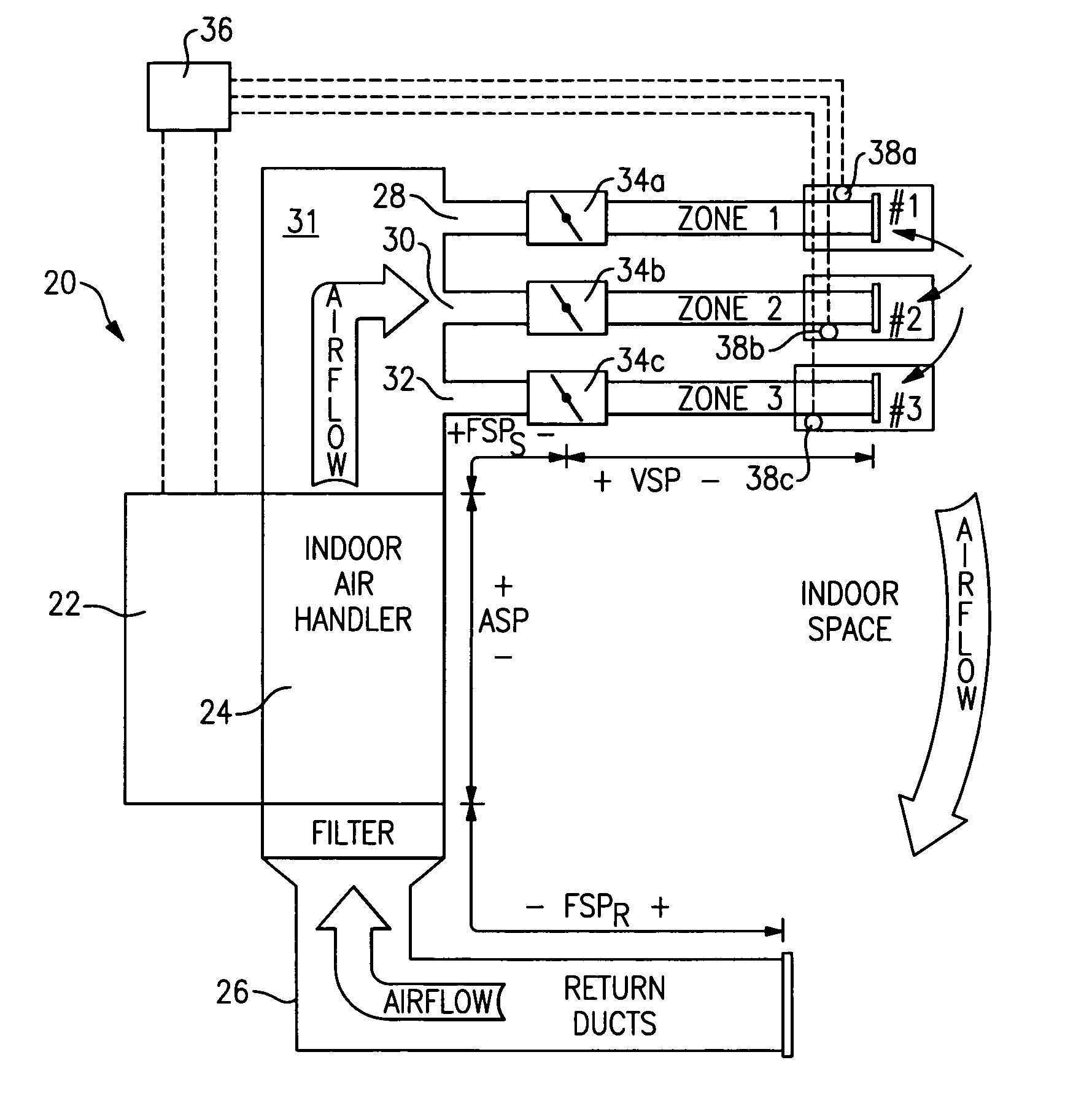
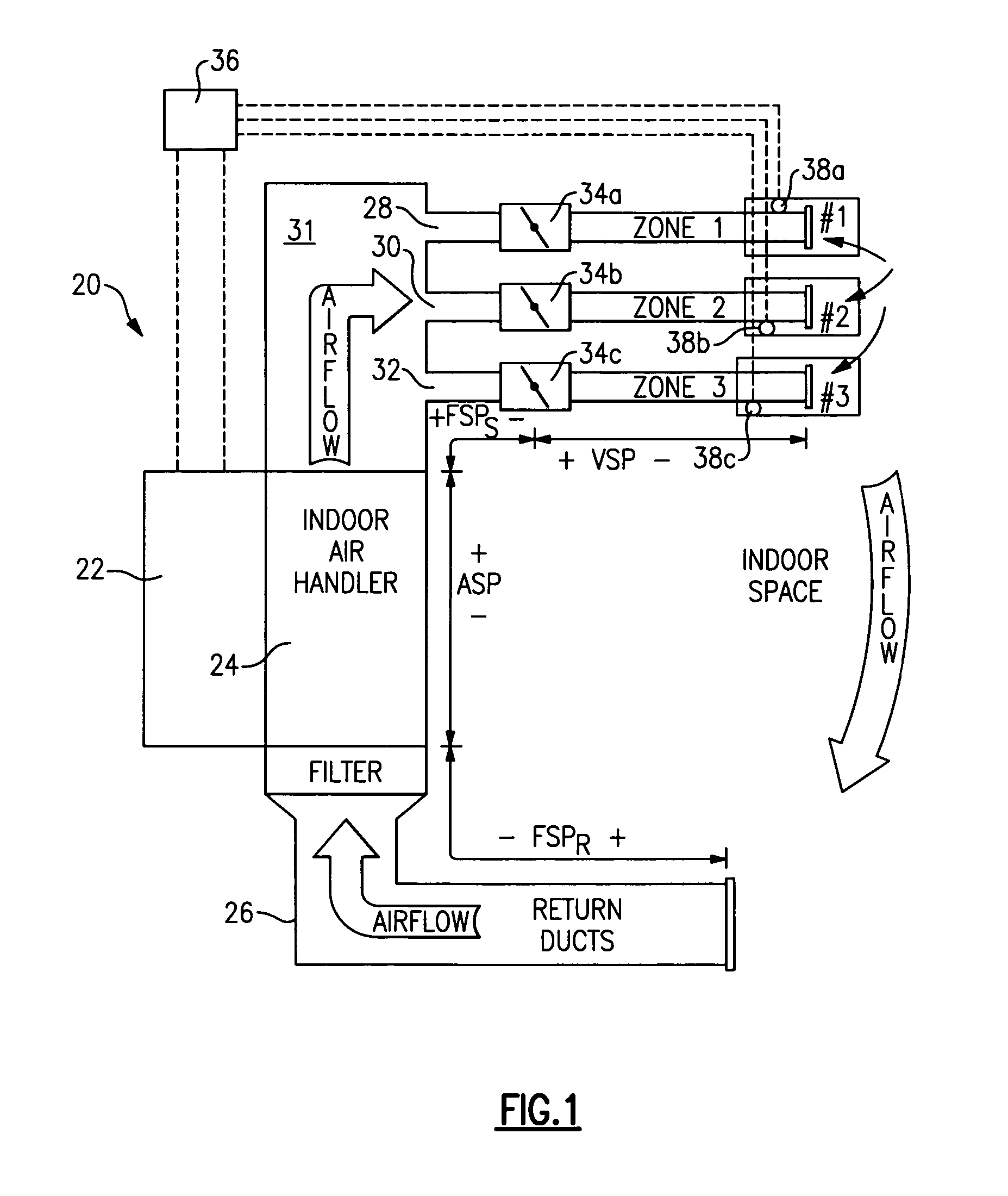
[0015] Referring to FIG. 1, a multi-zone HVAC system 20 is schematically illustrated. A temperature changing component 22 communicates with an indoor air handler 24. The temperature changing component 22 changes the condition of air and typically includes an indoor unit such as a furnace or heater coil, and / or an outdoor unit such as a condensing unit or a heat pump.

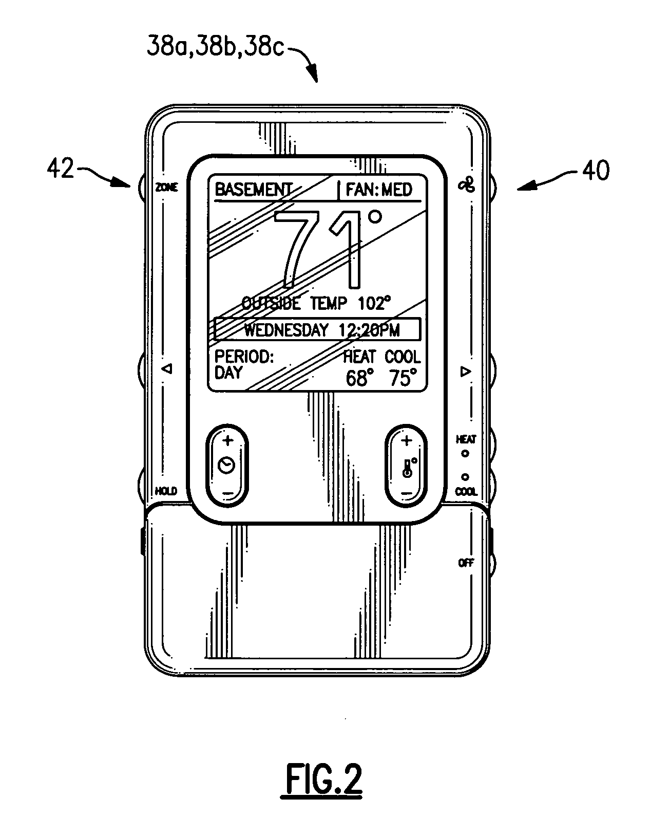
[0016] Associated with the indoor air handler 24 is a plenum 31. Supply ducts 28, 30, and 32 extend between the plenum 31 and distinct zones 1, 2, and 3. A damper 34a, 34b, and 34c is located within each supply duct 28, 30 and 32 respectively. A zone control 38a, 38b, and 38c (one shown in FIG. 2) is associated with distinct zones 1, 2, and 3 respectively.

[0017] A system control 36 communicates with each of the zone controls 38a, 38b, and 38c. The system control 36 is preferably a microprocessor or the like.

[0018] The zone controls 38a, 38b, and 38c allow a user to set desired temperatures, airflows etc. for each of t...


PUM


Abstract

A multi-zoned HVAC system includes a control for independently determining the amount of airflow delivered to each zone within the HVAC system. The control determines nominal zone airflow and continuous fan airflow levels for each zone based upon a user selected fan airflow level and the relative size of each zone in the HVAC system. The control determines the desired system airflow for the entire system once the continuous fan airflow levels for each zone are determined. The HVAC system provides a continuous fan airflow to each zone independently of the continuous fan airflow delivered to any other zone and irrespective of the relative size difference of the zones.

Description

[0001] This application claims priority to U.S. Provisional Patent Application Ser. No. 60 / 537,526, filed Jan. 20, 2004, and entitled “Continuous Fan Control in a Multi-Zone HVAC System.”BACKGROUND OF THE INVENTION [0002] The present invention relates to a method and control for the continuous fan airflow delivered to each of several zones in a multi-zone HVAC system, and more particularly to a control that allows a specified continuous fan airflow to be delivered simultaneously to all zones of the system. [0003] Conventional multi-zone HVAC systems include temperature changing components for changing the temperature and condition of air. Indoor air handlers drive air from the temperature changing component through supply ducts to several zones within a building. Each supply duct typically includes dampers that selectively restrict airflow into each zone to achieve a desired temperature. [0004] Conventional systems have traditionally offered a continuous fan function that provides s...

Claims


Application Information

Patent Timeline
Patent Type & Authority Applications(United States)
IPC IPC(8): F24F3/044F24F11/00
CPCF24F3/0442Y02B30/767F24F11/0012F24F11/0001F24F11/30F24F2110/10Y02B30/70F24F11/77F24F11/80F24F11/523F24F11/63F24F13/10F24F11/62
Inventor SHAH, RAJENDRA K.
Owner CARRIER CORP
Why Eureka
Try Eureka