3D printing imaging calibration method and 3D printing imaging calibration system

A technology of 3D printing and calibration method, applied in the field of 3D printing, can solve the problems of bulky, inconvenient operation and inconvenient portability of the two-dimensional image measuring instrument

Active Publication Date: 2017-06-13
HANS LASER TECH IND GRP CO LTD
View PDF5 Cites 18 Cited by
  • Summary
  • Abstract
  • Description
  • Claims
  • Application Information

AI Technical Summary

Problems solved by technology

However, the two-dimensional image measuring instrument is bulky and inconvenient to carry, and it is impossible to debug the DLP device at the customer site; moreover, the debugging process of the two-dimensional image measuring instrument is complicated and inconvenient to operate

Method used


Image

  • 3D printing imaging calibration method and 3D printing imaging calibration system
  • 3D printing imaging calibration method and 3D printing imaging calibration system
  • 3D printing imaging calibration method and 3D printing imaging calibration system

Examples


Embodiment Construction

[0042] In order to make the object, technical solution and advantages of the present invention clearer, the present invention will be further described in detail below in conjunction with the accompanying drawings and embodiments. It should be understood that the specific embodiments described here are only used to explain the present invention, not to limit the present invention.

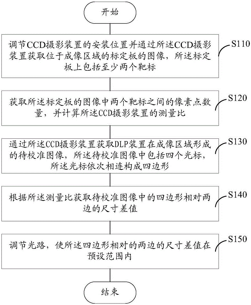
[0043] Such as figure 1 What is shown is a flow chart of the 3D printing imaging calibration method in one embodiment. A 3D printing imaging calibration method, comprising:

[0044] Step S110: adjusting the installation position of the CCD imaging device and acquiring the image of the calibration plate located in the imaging area through the CCD imaging device, and the calibration plate includes at least two targets.

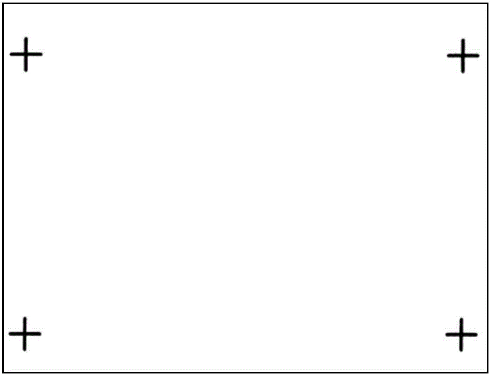
[0045] In one embodiment, the calibration board adopts a standard cross target calibration board, wherein the cross targets are located at four angles of the calibration board. Wh...


PUM


Abstract

The present invention relates to a 3D printing imaging calibration method and a 3D printing imaging calibration system. According to the 3D printing imaging calibration method, the image of a calibration plate positioned in an imaging region is acquired through a CCD imaging device; the measurement ratio of the CCD imaging device is calculated according to the acquired image of the calibration plate; according to the measurement ratio of the CCD imaging device, the size difference between the two opposite edges of a quadrilateral formed by four cursors of a DLP device in the imaging region is calculated; and by adjusting an optical path, the size difference between the two opposite edges of the quadrilateral formed by the four cursors of the DLP device in the imaging region is adjusted. With the 3D printing imaging calibration method of the present invention, the size of the projecting image of the imaging plane (exposure plane) of the DLP device can be quickly and accurately calibrated in a non-contact manner. In addition, the invention provides the 3D printing imaging calibration system.

Description

technical field [0001] The invention relates to the technical field of 3D printing, in particular to a 3D printing imaging calibration method and system. Background technique [0002] Digital Light Processing (DLP) 3D printer is a technology based on digital light processing. This technology first processes the image signal digitally, and then prints the model. The principle is to emit a certain wavelength from the LED light source. When the light is decomposed into three primary colors R, G, and B by a prism, it is projected to the DMD chip. Among them, the DMD chip includes a plurality of tiny lenses, each of which can rotate freely between -10° and +10° and is positioned by electric charges. After the signal input is processed, it acts on the DMD chip to control the deflection of the lens. The incident light is reflected by the lens on the DMD chip to the projection lens and then projected into an image. During the imaging process of the 3D printer, the incident light w...

Claims


Application Information

Patent Timeline
Patent Type & Authority Applications(China)
IPC IPC(8): B29C64/135B29C64/30B33Y40/00
CPCB33Y40/00
Inventor 南威袁剑谢祖云齐志宏高云峰
Owner HANS LASER TECH IND GRP CO LTD
Why Eureka
Try Eureka