Alignment mark system and method to improve wafer alignment search range

a technology of alignment marks and search ranges, applied in the field of alignment marks system and method to improve the search range of wafer alignment marks, can solve the problems of large errors in substrate placement, undermine the proper operation of fine alignment systems, and confusion in determining the proper alignment position of substrates, so as to increase the capture range of diffraction pattern detection methods and improve the efficiency of tools. operation

Inactive Publication Date: 2005-07-21
GLOBALFOUNDRIES INC
View PDF9 Cites 11 Cited by
  • Summary
  • Abstract
  • Description
  • Claims
  • Application Information

AI Technical Summary

Benefits of technology

[0008] The present invention is a system and method for use with alignment marks and search algorithms of diffraction pattern detection tools. In particular, the system and method of the invention significantly increases the capture range of diffraction pattern detection methods and enables more efficient operation of tools employing such detection methods.

Problems solved by technology

These multiple peaks can cause confusion in determining the proper aligned position of the substrate.
Thus, exceeding this capture range during a search for the proper aligned position of the substrate can lead to large errors in substrate placement and undermine the proper operation of a fine alignment system.

Method used


Image

  • Alignment mark system and method to improve wafer alignment search range
  • Alignment mark system and method to improve wafer alignment search range
  • Alignment mark system and method to improve wafer alignment search range

Examples


first embodiment

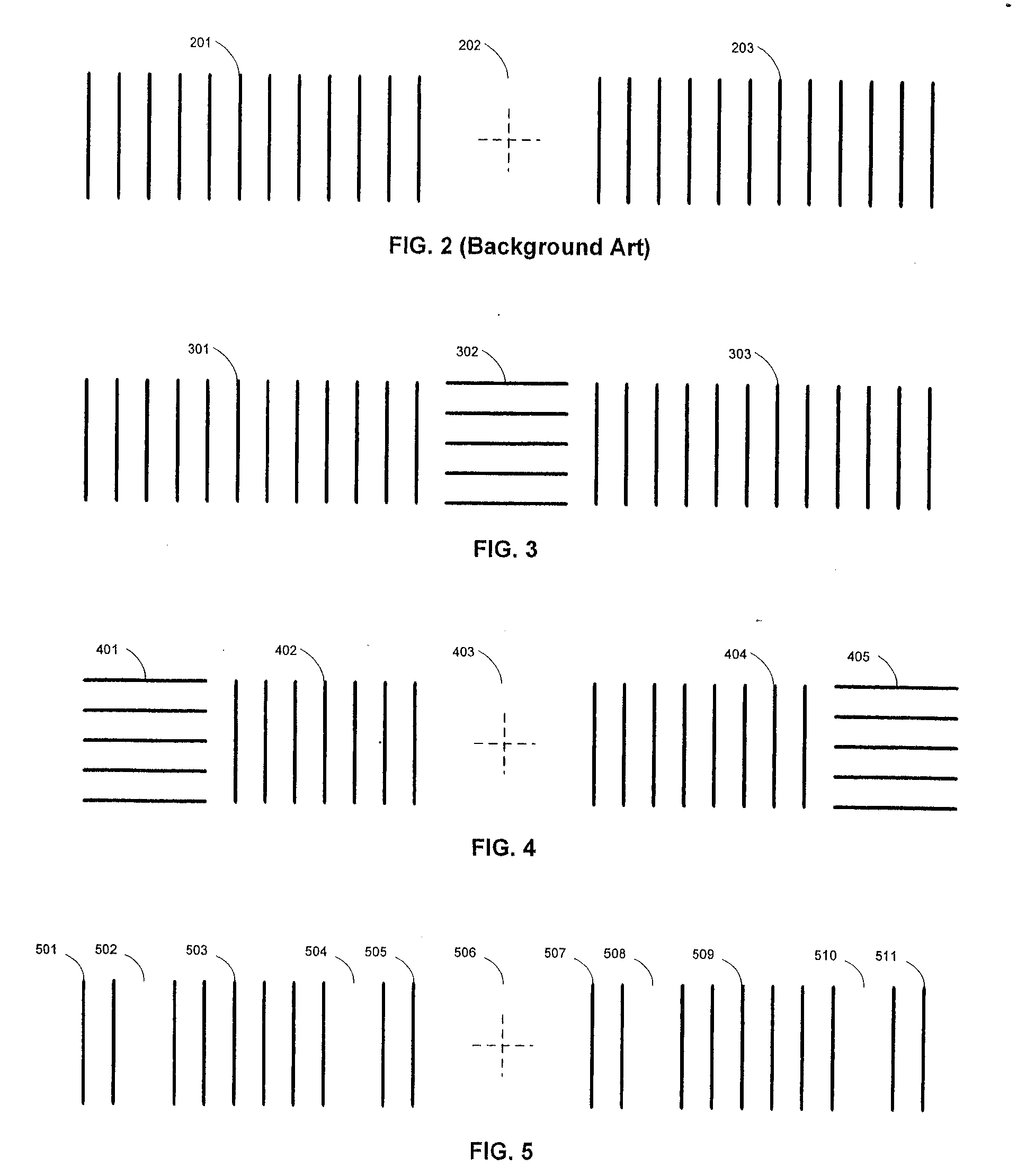
[0025]FIG. 2 shows an example of alignment marks 201, 203 used in the background art of alignment systems. FIG. 3 shows the alignment mark of the present invention. The embodiment shown in FIG. 3 is an alignment mark comprising an X mark 301, 303 with a segment of a Y mark 302 in the X mark 301, 303. In the non-limiting example shown in FIG. 3, the segment of a Y mark 302 in the X mark 301, 303 is located in the middle portion of the X mark 301, 303. Moreover, a Y mark further comprising a segment of an X mark in the Y mark can also be represented by FIG. 3 when the figure is rotated by + / −90°.

second embodiment

[0026]FIG. 4 shows the alignment mark of the present invention. The embodiment shown in FIG. 4 is an alignment mark comprising an X mark 402, 404, wherein the segment of a Y mark 401, 405 in an X mark 402, 404 are located at each end of the X mark. Moreover, as discussed above for FIG. 3, a Y mark further comprising a segment of an X mark in the Y mark can also be represented by FIG. 4 when the figure is rotated by + / −90°.

third embodiment

[0027]FIG. 5 shows the alignment mark of the present invention. The embodiment shown in FIG. 5 is an alignment mark comprising an X mark 501, 503, 505, 507, 509, 511, wherein at least one segment or line of the X mark 502, 504, 508, 510 is removed. In general, segments / lines of either an X mark or a Y mark may be removed to eliminate regions of the X mark and Y mark that cause false alignments. In addition, a method for designing the alignment mark may further comprise removing a segment / line in the X mark that at least one of contribute the majority of the signal strength and require minimum signal strength. Further, removing a segment / line may further comprise replacing the removed segment / line with marks of an opposite axis to provide, for example, a coarse position check.

[0028] Moreover, at least one segment / line of an X mark and / or at least one segment / line of a Y mark may be removed and replaced by at least one segment / line with a different orientation than the X mark and / or Y...


PUM

PropertyMeasurementUnit
widthaaaaaaaaaa
widthaaaaaaaaaa
signal strengthaaaaaaaaaa

Abstract

The present invention is a system and method for use with alignment marks and search algorithms of diffraction pattern detection tools. The system and method of the invention significantly increases the capture range of diffraction pattern detection methods and enable more efficient operation of tools employing such detection methods.

Description

BACKGROUND OF INVENTION [0001] 1. Field of the Invention [0002] The present invention is a system and method for using alignment marks on a substrate for alignment with a photolithographic system. [0003] 2. Background of the Invention [0004] Alignment tools, such as photolithographic systems, typically do a global search to provide a coarse alignment of a substrate that is loaded into the system. This coarse alignment locates alignment marks within a specified tolerance and removes large translation and rotation errors in the placement of the substrate in the system before a finer grained alignment is performed for the substrate. Removal of these potentially large errors during coarse alignment enables fine alignment systems to efficiently capture alignment marks on the substrate during the fine alignment process. [0005] Fine alignment systems generally use one of three types of detection methods: bright field, dark field and diffraction pattern. Of these methods, diffraction patter...

Claims


Application Information

Patent Timeline
Patent Type & Authority Applications(United States)
IPC IPC(8): G03F9/00H01L21/76H01L23/544
CPCG03F9/7049G03F9/7088G03F9/7076
Inventor FROEBEL, ROBERT T.SONNTAG, PAUL D.SULLIVAN, PETER J.
Owner GLOBALFOUNDRIES INC
Why Eureka
Try Eureka