
Visual and steering-controllable abscess debridement device

A technology of abscess and curved tube, applied in the field of abscess debridement device, to achieve good plastic effect

Pending Publication Date: 2021-09-17
SHANGHAI FIRST PEOPLES HOSPITAL
View PDF2 Cites 2 Cited by
  • Summary
  • Abstract
  • Description
  • Claims
  • Application Information

AI Technical Summary

Problems solved by technology

However, there is no relevant report about a visual and controllable abscess debridement device that is easy to use, can clearly display the operating field of view, and achieve the purpose of adequate debridement of large abscess cavities

Method used


Image

  • Visual and steering-controllable abscess debridement device
  • Visual and steering-controllable abscess debridement device
  • Visual and steering-controllable abscess debridement device

Examples


Embodiment 1

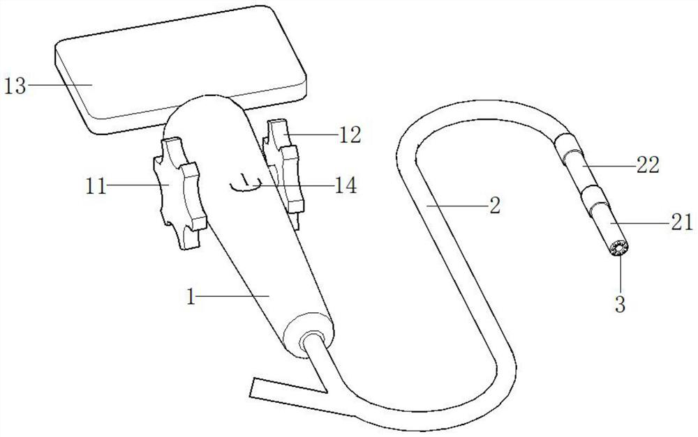
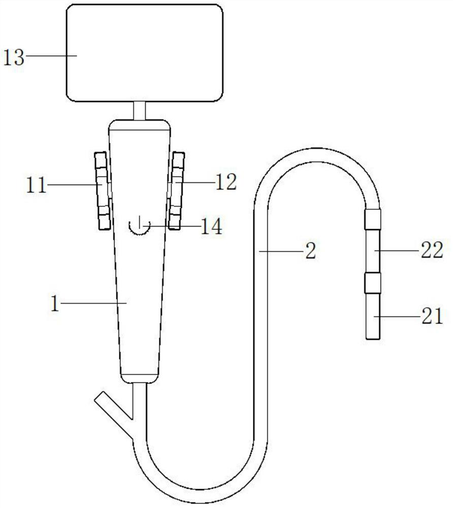
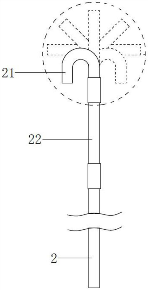
[0037] Please see attached Figure 1-2 , figure 1 It is a three-dimensional structural schematic diagram of a visualized and controllable abscess debridement device of the present invention, figure 2 It is a top view of a visualized, steering-controllable abscess debridement device of the present invention. A visualized, steering-controllable abscess debridement device. The visualized, steering-controllable abscess debridement device includes a handle 1 and a pipeline body 2; Two adjustment buttons 12, the surface is provided with a display screen 13 and a switch button 14, and the inside is provided with a power module (not shown in the figure); the pipeline body 2 is a hollow structure, and the end is connected to the handle 1 in a Y-shaped structure; The top of the pipe body 2 communicates with the first curved pipe 21 and the second curved pipe 22; the first curved pipe 21 is connected above the second curved pipe 22, and the inner side of the first curved pipe 21 is pr...

Embodiment 2

[0040] This embodiment is basically the same as Embodiment 1, the difference is that in this embodiment, the number of curved tubes connected to the top of the pipe body 2 and the number of adjustment buttons can be designed according to needs, so as to achieve more directions and larger angles at the top of the pipe body 2 The range of rotation is convenient for selective debridement according to the size of the abscess cavity during the operation.

[0041] A visualized and steering-controllable abscess debridement device of the present invention can expand the capture range of the lighting and camera system at the top of the pipeline body by connecting two curved tubes at the top of the pipeline body, and can realize abscess cavity with a large area Sufficient debridement purpose; the first bending tube and the second bending tube are made of tungsten wire braided mesh material or 360° bendable mechanical arm, which has a certain damping property, which is convenient for the ...


PUM


Abstract

The invention relates to a visual and steering-controllable abscess debridement device. The visual and steering-controllable abscess debridement device comprises a handle and a pipeline body; a first adjusting button and a second adjusting button are arranged on the side edge of the handle, a display screen and a switch button are arranged on the surface of the handle, and a power module is arranged in the handle; the pipeline body is of a hollow structure, and the tail end of the pipeline body is of a Y-shaped structure and is connected with the handle; the top end of the pipeline body is communicated with a first bent pipe and a second bent pipe, and an illumination camera system is arranged on the periphery of the inner side of the top of the first bent pipe; the first adjusting button and the second adjusting button are connected with the two sides of the top end of the first bent pipe and the two sides of the top end of the second bent pipe through steel wires arranged in the pipe wall of the pipeline body respectively; and a negative pressure device or a flushing device or a pair of operating forceps can be externally connected to the Y-shaped structure at the tail end of the pipeline body. The visual and steering-controllable abscess debridement device has the advantages that use is convenient, the operating view can be clearly displayed, and meanwhile the purpose of fully debridement of the large abscess cavity is achieved.

Description

technical field [0001] The invention relates to the technical field of medical devices, in particular to a visualized and controllable abscess debridement device. Background technique [0002] Abscess is a localized pus accumulation in tissues, organs or body cavities due to necrosis and liquefaction of diseased tissues during acute infection. There is a complete pus wall around. The means of its clinical treatment is usually to puncture the pus wall of the abscess and drain the pus inside. However, the drainage method has the problem that pus remains in the pus wall and cannot be removed in time, and when pus adheres to the inner wall of the abscess cavity, the existing treatment methods often cannot fully clean the abscess cavity. There are also operators who design the insertion end of the drainage tube as a bendable structure, so as to facilitate the drainage of pus in the dead corner of the abscess cavity, but because this treatment method is operated under blind visi...

Claims


Application Information

Patent Timeline
Patent Type & Authority Applications(China)
IPC IPC(8): A61M1/00A61M3/02A61M25/01A61B90/30A61B90/00A61B10/06
CPCA61M3/0279A61B10/06A61B90/30A61B90/361A61M25/0105A61M2025/0177
Inventor 尹华斌李勇爱宋滇文孟通魏子恒
Owner SHANGHAI FIRST PEOPLES HOSPITAL
Learn More