Phase comparator, pll circuit, information regeneration processing apparatus, optical disc regenerating apparatus, and magnetic disc regenerating apparatus

A phase comparator, information regeneration technology, applied in recording signal processing, signal processing using self-timing codes, optical discs, etc., can solve problems such as deterioration, and achieve the effect of expanding the capture range

Inactive Publication Date: 2009-10-28
PANASONIC CORP
View PDF1 Cites 4 Cited by
  • Summary
  • Abstract
  • Description
  • Claims
  • Application Information

AI Technical Summary

Problems solved by technology

Therefore, there is a problem that the capture characteristic (capture range; capture range) of the clock generation circuit is greatly deteriorated when the frequency deviation is large and the delay of the phase control loop is large.

Method used


Image

  • Phase comparator, pll circuit, information regeneration processing apparatus, optical disc regenerating apparatus, and magnetic disc regenerating apparatus
  • Phase comparator, pll circuit, information regeneration processing apparatus, optical disc regenerating apparatus, and magnetic disc regenerating apparatus
  • Phase comparator, pll circuit, information regeneration processing apparatus, optical disc regenerating apparatus, and magnetic disc regenerating apparatus

Examples


no. 1 Embodiment approach

[0047] Next, a first embodiment of the present invention will be described with reference to the drawings.

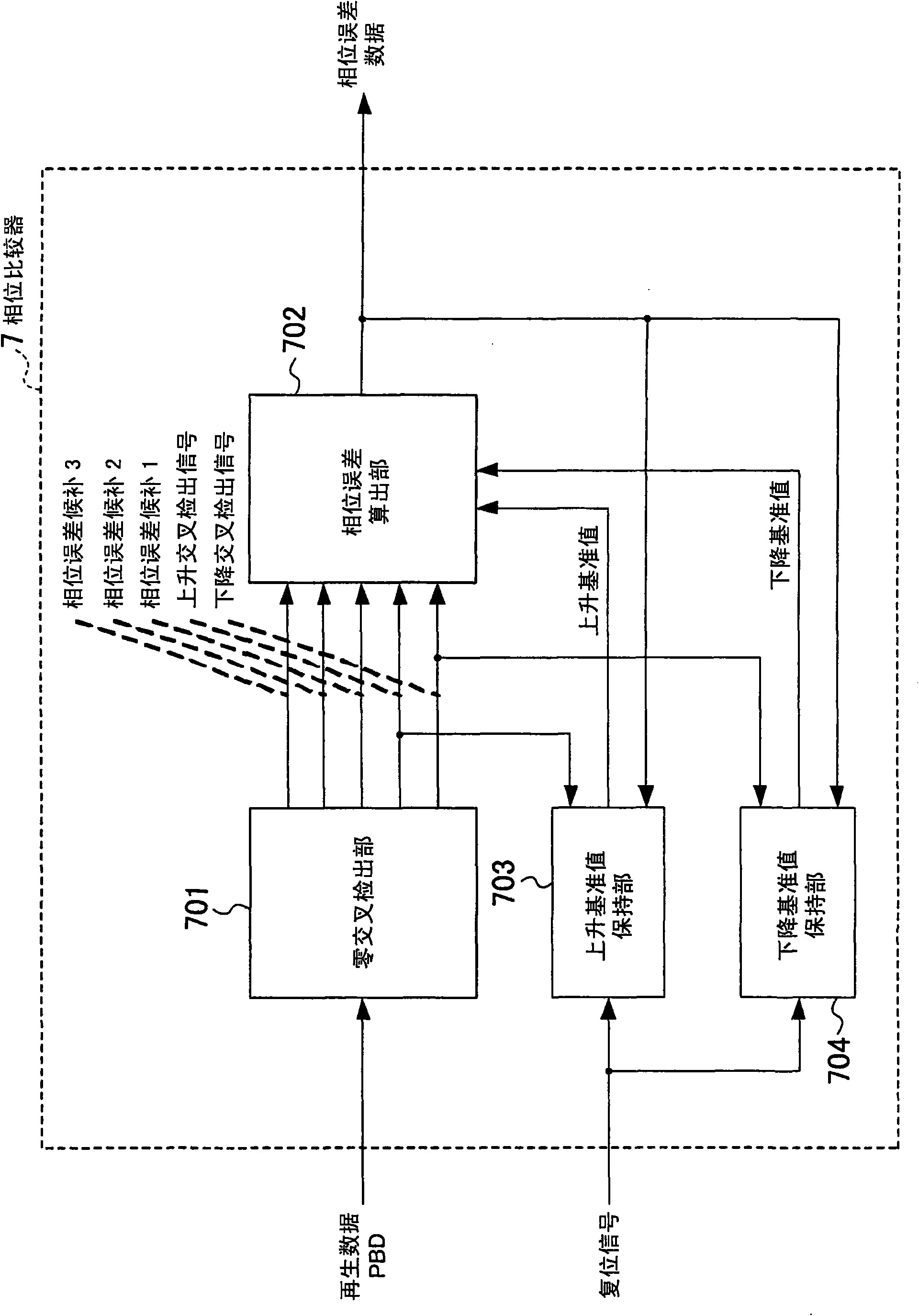
[0048] figure 1 The configuration of the phase comparator according to the first embodiment of the present invention is shown. In this figure, 7 is a phase comparator, which calculates and outputs the phase error based on the reproduced data; 701 is a zero-cross detection part, which detects the crossing of the reproduced data from the rising direction or from the falling direction and the zero level, and at the same time, sets zero The cross sampling data and the two sampling data located before and after the zero cross sampling data, a total of three reproduced data are phase error candidates; The candidate of the value is used as the phase error, and the candidate closest to the falling reference value is calculated when falling, and it is used as the phase error; 703 is a rising reference value holding part, and the phase error is updated as a new rising reference...

no. 2 Embodiment approach

[0059] Next, a phase comparator according to a second embodiment of the present invention will be described.

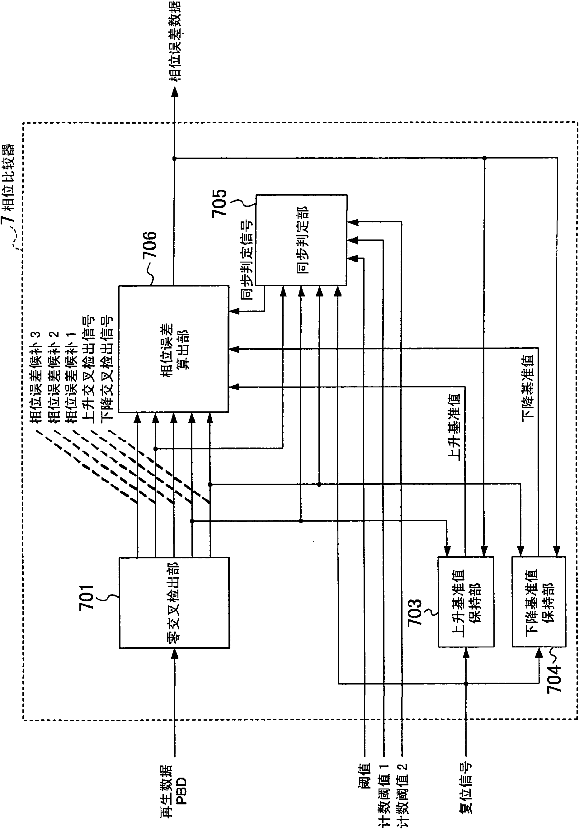
[0060] exist figure 2 In the phase comparator 7, 701 is a zero-cross detector, 703 is a rising reference value holding unit, 704 is a falling reference value holding unit, 705 is a synchronization determination unit, and 706 is a phase error calculation unit. Since the above-described zero-cross detector 701 , rising reference value holding unit 703 , and falling reference value holding unit 704 are the same as those in the first embodiment, description thereof will be omitted.

[0061] Figure 9 The internal configuration of the above-mentioned synchronization determination unit 705 is shown. In the figure, 730 is a zero-cross counting unit, 731 is a zero-crossing count determination unit, 732 is a zero-cross data determination unit, 733 is a zero-cross data counting unit, and 734 is a zero-cross data count determination unit.

[0062] The aforementioned synchron...


PUM


Abstract

In a phase comparator used for a synchronous clock extraction circuit that extracts a clock synchronized with regenerated data, a zero cross detection unit (701) outputs a rising cross detection signal, a trailing cross detection signal, and three phase error candidates that are three consecutive sample data from the regenerated data. A rising reference value holding unit (703) and a trailing reference value holding unit (704) output a rising reference value and a trailing reference value, respectively. When a phase error calculation unit (702) receives the rising cross detection signal or the trailing cross detection signal, it outputs the sample data of which the absolute value of the difference between the rising or trailing reference value and the sample data among three sample data including zero cross sample data is minimum as a phase error. This phase error is held in the rising reference value holding unit (703) or the trailing reference value holding unit (704) as the rising or trailing reference value used at the time of the next phase error calculation. Accordingly, a wide capture range can be realized.

Description

technical field [0001] The present invention relates to a reproduced signal processing circuit for extracting data recorded on the recording medium from an optical disk or a magnetic disk, and synchronously extracting a synchronous clock. Specifically, it relates to a phase comparator used for extracting the synchronous clock. Background technique [0002] image 3 An example of a reproduction signal processing circuit in a conventional general information reproduction processing device is shown. [0003] In this figure, 1 is a recording medium, 2 is an optical pickup, 3 is an analog front end, 4 is an A / D converter, 5 is a digital filter, 6 is a maximum likelihood decoder, 7 is a phase comparator, 8 and 11 is a loop filter, 9 is a VCO, 10 is a frequency comparator, 12 is a digital signal processing circuit, and 13 is a synchronous clock extraction circuit. [0004] Next, an outline of the operation will be described. When reproducing data written in a recording medium suc...

Claims


Application Information

Patent Timeline
Patent Type & Authority Applications(China)
IPC IPC(8): G11B20/14H03L7/085H03L7/087H03L7/10
CPCG11B20/10009G11B20/14G11B2220/2537H03L7/091G11B20/10425G11B20/10222G11B20/10046H04L7/0334
Inventor 山本明白川佳则冈本好史毛利浩喜
Owner PANASONIC CORP
Why Eureka
Try Eureka