Optical scanning using vibratory diffraction gratings

a technology of vibratory diffraction grating and optical scanning, which is applied in the field of optical scanning system, can solve the problems of large dynamic mirror deformation (greater than /8 mechanical), adversely affecting optical resolution, and dynamic deformation of the mirror plate, and achieves enhanced optical resolution, low operating voltage, and high scan frequency

Inactive Publication Date: 2005-07-21
NAT UNIV OF SINGAPORE
View PDF45 Cites 69 Cited by
  • Summary
  • Abstract
  • Description
  • Claims
  • Application Information

AI Technical Summary

Benefits of technology

[0020] An object of the invention is to provide a diffraction grating scanner having a wider optical scan angle and high resonant frequencies leading to high scan frequencies

Problems solved by technology

One of the critical drawbacks of this micromirror reflection technology is large dynamic mirror deformation (greater than λ/8 mechanical).
This phenomenon is due to the fabrication-limited thickness and high out-of-plane acceleration forces, which cause the mirror plate to deform dynamically during scanning, thus adversely affecting the optical resolution.
One of the most prominent problems of the scanning micromirror entails the dynamic deformation of the mirror plate.
Micromachined mirrors are normally much thinner than conventional macro-scanning mirrors, therefore, at high scanning frequencies, micromachined mirrors deform dynamically, which introduces time-dependent optical aberrations and severely limits the optical resolution.
However, the reduction of scanning beam divergence caused by beam diffraction and micromirror's dynamic deformation is still a big challenge for high-speed scanning micromirror developers.
However, increasing the mirror thickness also increases the mass, and in order to maintain a high scanning frequency, the stiffness of the mirror suspension has to be increased.
This results in a very high driving voltage and considerable power consumption.
However, this miniaturized scanner has some critical drawbacks.
Firstly, the scanning rate is severely limited to a few hundred Hz since the polysilicon micromotor shown in FIG. 4 lacks the potential to spin at a high speed.
Secondly, the driving voltage required for motion to be continuous is very large, typically hundreds of volts.
Thirdly, the scanner is not free from wear and tear especially when high spinning speed is required, thus severely limiting the lifetime of

Method used


Image

  • Optical scanning using vibratory diffraction gratings
  • Optical scanning using vibratory diffraction gratings
  • Optical scanning using vibratory diffraction gratings

Examples


examples

[0095]FIG. 18 shows an SEM image of the central part of the vibrating grating laser scanner fabricated and tested according to the fourth embodiment of the present invention shown in FIG. 12.

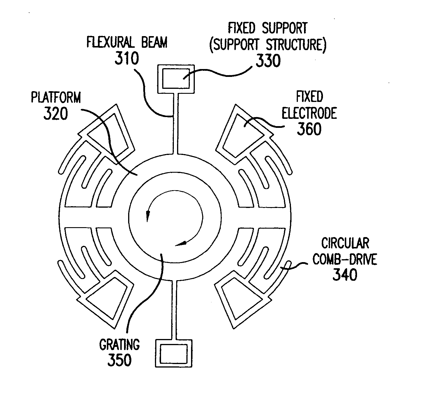
[0096] The resonant grating scanner was fabricated using a 3 -layer Polysilicon surface micromachining process. The vibrating structures including the electrostatic comb-drive and diffraction grating was suspended 2 μm above the substrate by 8 sets of folded-beam flexures with beams having a length of 300 μm, width of 3 μm and thickness of 3.5 μm, and 2 sets of folded-beam flexures with beams having a length of 180 μm, width of 2 μm and thickness of 2 μm. This free-standing design eliminates any contact-friction between the vibrating structure and substrate. Two opposing interdigitated laterally-driven electrostatic comb-drives, each having a total number of 123 movable fingers with finger length of 50 μm, width of 3 μm, thickness of 3.5 μm, finger gap of 2 μm and overlap length of 25 μm, were ...


PUM


Abstract

An optical scanning apparatus includes an in-plane vibratory mass platform having at least one diffraction grating formed thereon as the scanning element, at least one flexure structure that connects the mass platform to at least one fixed support, and at least one driving actuator that drives the mass platform into an in-plane vibratory motion which can be rotational and/or translational. The apparatus may also be formed by a mass platform having at least one diffraction grating formed thereon as the scanning element, at least one driving actuator connected to the mass platform through at least one flexure structure. The driving actuator drives the mass platform into an in-plane vibratory motion.

Description

[0001] This application claims the benefit of the U.S. Provisional Application No. 60 / 537,249, which is hereby incorporated by reference.BACKGROUND OF THE INVENTION [0002] 1. Field of the Invention [0003] The invention relates to an optical scanning system using a vibratory or oscillatory diffractive element made by micromachined or Micro-Electro-Mechanical (MEM) technology. [0004] 2. Discussion of the Related Art [0005] Optical scanning devices have numerous applications in the following fields: manufacturing, medicine, military hardware, information systems and communications. These applications include but not limited to optical switching, biomedical imaging (optical coherence tomography, scanning laser confocal microscopy etc.), laser printing, spectrometer, microdisplays, image projection and acquisition, laser materials processing (marking, drilling, coding trimming etc.), and stereolithography. [0006] The primary function of an optical scanner device is to steer an electromag...

Claims


Application Information

Patent Timeline
IPC IPC(8): G02B26/08G02B26/10H02N1/00
CPCG02B26/0808H02N1/008G02B26/106B81B3/0062B81B2201/033B81B2201/047B81B2203/0109B81B2203/056B33Y30/00
Inventor ZHOU, GUANGYAVJ, LOGEESWARANCHAU, FOOK SIONG
Owner NAT UNIV OF SINGAPORE
Why Eureka
Try Eureka