Method and system of calibrating the control delay time

a control delay and time delay technology, applied in the field of methods and systems can solve the problems of system instability, the accuracy and reliability of the control delay time obtained by using such a method get lower and lower, and achieve the effect of effective adjustment of control delay time, ensuring accuracy of data read from memory when the control chip performs memory read operation, and achieving memory read efficiency

Inactive Publication Date: 2005-07-21
VIA TECH INC
View PDF1 Cites 9 Cited by
  • Summary
  • Abstract
  • Description
  • Claims
  • Application Information

AI Technical Summary

Benefits of technology

[0008] Therefore, the present invention provides a method and system of calibrating control delay time, and further effectively adjusts the control delay time to achieve optimization. Therefore, the accuracy of the data read from memory when the control chip performs the memory read operation can be assured and the efficiency of the memory read can be achieved.

Problems solved by technology

Since the default values cannot be adjusted according to factors such as the individual environment, element status or the circuit layout, the control delay time is not located at the optimal position, so factors that make the system unstable increase.
However, under the circumstance where the clock cycle gets higher, the accuracy and the reliability of the control delay time obtained by using such a method gets lower and lower.

Method used


Image

  • Method and system of calibrating the control delay time
  • Method and system of calibrating the control delay time
  • Method and system of calibrating the control delay time

Examples


Embodiment Construction

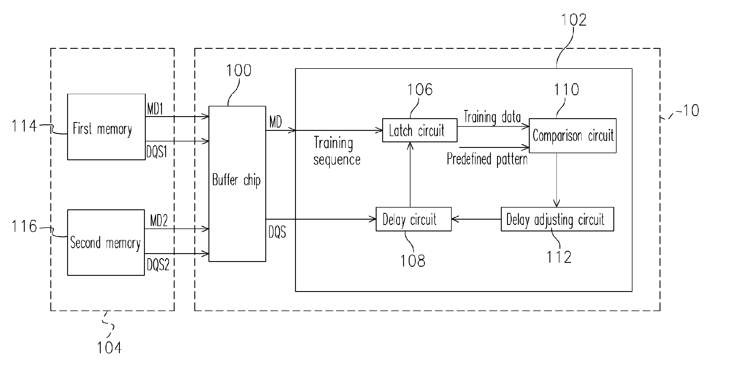
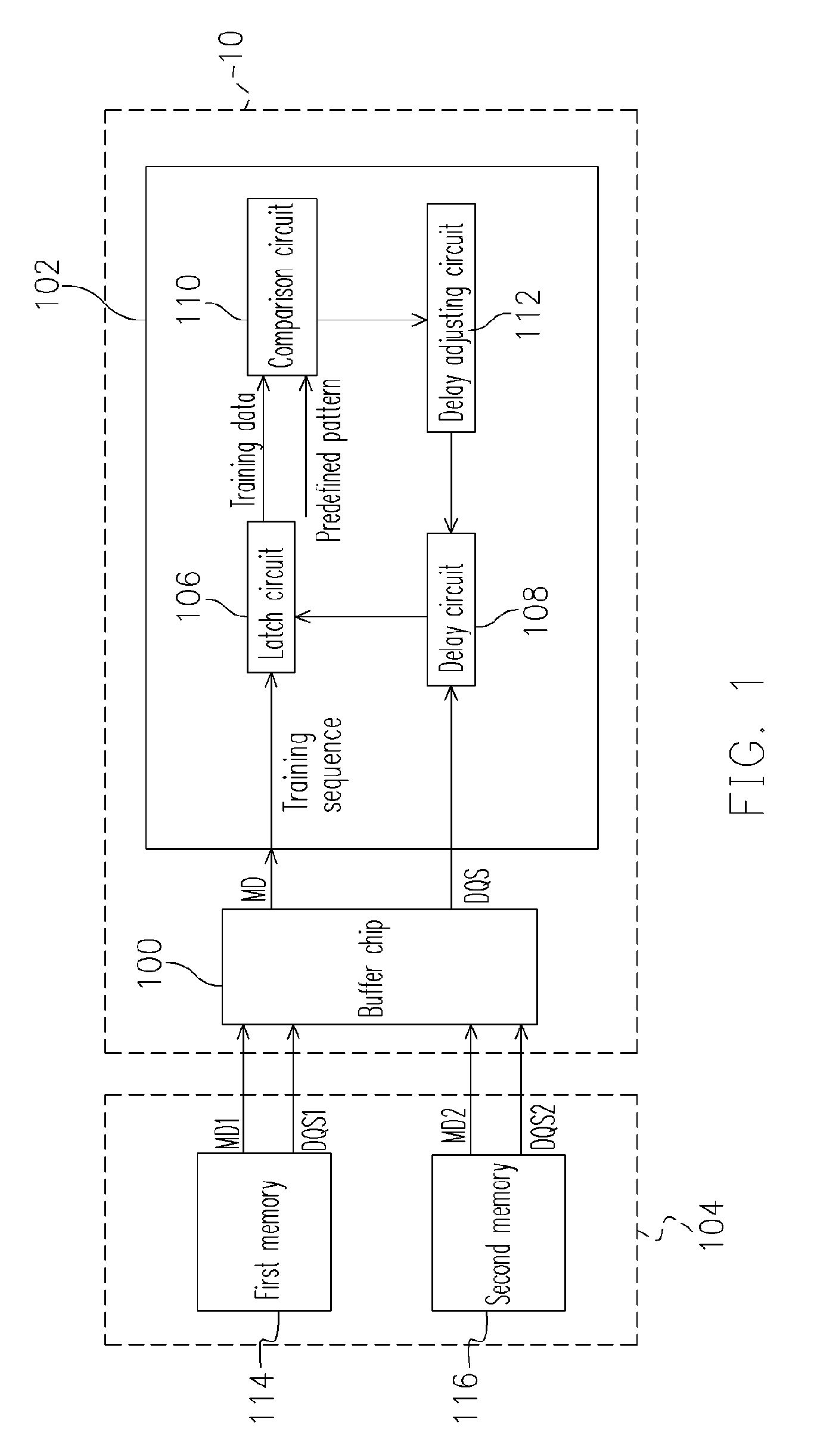
[0016]FIG. 1 schematically shows a block diagram of a system of calibrating the control delay time of a preferred embodiment according to the present invention. As shown in the diagram, the system of calibrating the control delay time 10 comprises a buffer chip 100 and a control chip 102 (e.g. a north bridge chip). Wherein, the buffer chip 100 connects to the control chip 102 and a memory 104. The buffer chip 100 mentioned above may be integrated into the memory 104 or separated from the memory 104 as designed. The control chip 102 comprises a latch circuit 106, a delay circuit 108, a comparison circuit 110 and a delay adjusting circuit 112.

[0017] Herein, in order to adapt to the control chip 102 for rapidly reading the data from memory, so as to improve the processing speed and the performance of the computer system. The memory 104 comprises a first memory 114 and a second memory 116. The DDR SDRAM is used as the first memory 114 and the second memory 116 to access data. That is, ...


PUM


Abstract

The present invention relates to a method and system of calibrating the control delay time, providing effective calibration for the control delay time provided by a control chip to reach the optimal effect for effective reading. The control chip uses the connected buffer chip to produce a training sequence when the buffer chip enters a training mode. After the control chip receives the training sequence, the control chip will produce the training data to compare with the predefined pattern inside it and adjust the control delay time. Finally, the control chip will produce an optimal adjusting control delay time to allow the data strobe signal to control the effective retrieved range of the data.

Description

CROSS-REFERENCE TO RELATED APPLICATION [0001] This application is a continuation of a prior application Ser. No. 10 / 249,561, filed Apr. 18, 2003, which claims the priority benefit of Taiwan application serial no. 91113583, filed on Jun. 21, 2002.BACKGROUND OF THE INVENTION [0002] 1. Field of Invention [0003] The present invention generally relates to a method and system of calibrating the control delay time, and more particularly, to a calibration method and system used to define the effective retrieved range of the control delay time to obtain the optimal control delay time when the control chip is performing the reading operation. [0004] 2. Description of Related Art [0005] Since the development of the data processing speed for the currently used personal computer is getting faster and faster, the requirement of the efficiency and accuracy for accessing the data stored in memory needs to be relatively improved, so as to effectively adapt with the data processing speed of the perso...

Claims


Application Information

Patent Timeline
Patent Type & Authority Applications(United States)
IPC IPC(8): G01D18/00G06F11/00G06F19/00G11C7/10G11C7/22G11C11/4076G11C11/4096H03H11/26
CPCG11C2207/2254G11C7/1006G11C7/1051G11C7/1066G11C7/1072G11C11/4096G11C7/1093G11C7/22G11C7/222G11C11/4076G11C7/1078
Inventor LIOU, MING-SHI
Owner VIA TECH INC
Why Eureka
Try Eureka