Image display method

a technology of image display and display method, which is applied in the direction of instruments, television systems, signal generators with optical-mechanical scanning, etc., can solve the problems of difficult to strictly set the duty ratio, display uniformity, and possible blue phenomenon

Inactive Publication Date: 2005-07-21
KK TOSHIBA
View PDF9 Cites 34 Cited by
  • Summary
  • Abstract
  • Description
  • Claims
  • Application Information

AI Technical Summary

Problems solved by technology

A problem with the hold type display is a blur phenomenon that may occur when motion pictures are displayed.
Consequently, differences between signal line driving circuits make the display ununiform (a variation in brightness (i.e. luminance)).
However, it is difficult to strictly set the duty ratio.
However, this leads to an increase in power consumption.
Moreover, if the duty ratio is varied by blinking the back light, flickers may occur unless the back light can blink stably.
Thus, with the conventional methods, providing black display periods may cause a decrease in screen brightness or the like.
This may result in various problems.
It is known that a low subfield frequency may lead to “color breakup”.
As a result, color breakup may occur.
As a result, the hold effect of the eyes may cause similar color breakup.
Such a phenomenon strikes the observer as incongruous.
Further, if the display device is used for a long time, the observer may be fatigued.
However, this method fails to sufficiently suppress the color break up resulting from the hold effect.
However, substantially increasing the subfield frequency creates a new problem.
That is, loads on driving circuits for the display device may increase.
However, disadvantageously, the brightness of the image may generally decrease or the maximum brightness of the image must be increased.
As a result, it is difficult to obtain high-quality images.
Further, if color images are displayed on the basis of the field-sequentially additive color mixing system by dividing one frame into a plurality of subfields, then possible color breakup makes it difficult to obtain high-quality images.
Further, if the subfield frequency is increased to suppress the color breakup, loads on the driving circuits may disadvantageously increase.

Method used


Image

  • Image display method
  • Image display method
  • Image display method

Examples


first embodiment

[0050] First, a first embodiment of the present invention will be described.

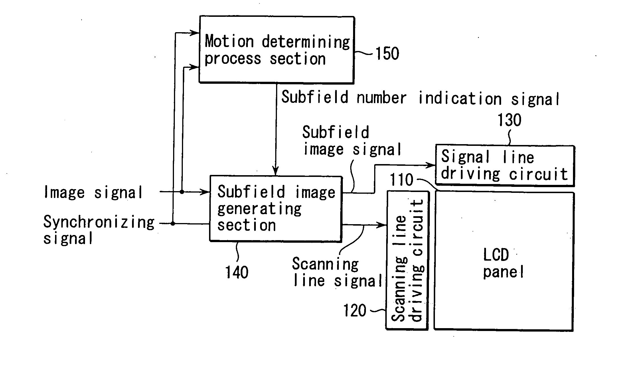
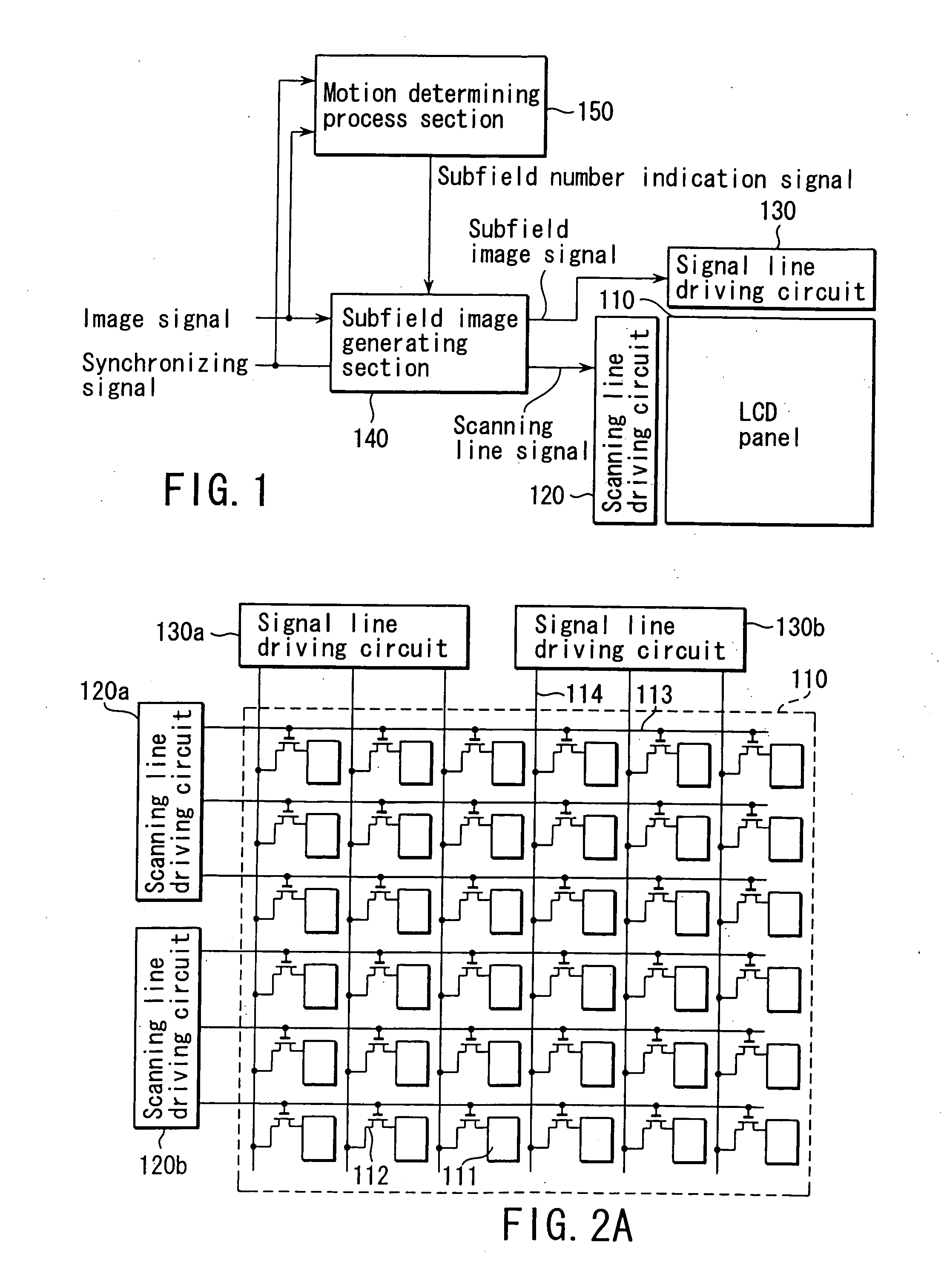
[0051]FIG. 1 is a block diagram schematically showing the configuration of a liquid crystal display device according to embodiments of the present invention. FIG. 2A is a diagram showing the configuration of a liquid crystal display module section (a liquid crystal display panel and peripheral circuits), shown in FIG. 1.

[0052] The liquid crystal display module section is composed of a liquid crystal display panel 110, a scanning line driving circuit 120 (120a, 120b) and a signal line driving circuit 130 (130a, 130b). The scanning line driving circuit 120 is supplied with a scanning signal by a subfield image generating section 140. The signal line driving circuit 130 is supplied with a subfield image signal by a subfield image generating section 140. Further, an image signal and a synchronizing signal are input to the subfield image generating section 140 and a motion determining process section 150. The s...

second embodiment

[0069] Now, a second embodiment of the present invention will be described.

[0070] In this embodiment, compared to the first embodiment, the first subfield has the lowest brightness, and the subsequent fields have a sequentially increasing brightness.

[0071]FIGS. 8A, 8B, and 8C show an example of this embodiment. As in the example shown in FIGS. 6A to 6D, FIG. 8A shows the brightness of the pixels of an input image. FIG. 8B shows an example in which images with the same brightness are displayed in the first and second subfields, respectively. In this example, a first and second subfield images (c-1) and (c-2) are generated in a brightness ratio R of 1 / 3 so that the average brightness is as shown in (c-3), as shown in FIG. 8C. Any remainder of the division between the two brightness values is added to or subtracted from the corresponding brightness in the first subfield.

[0072] The occurrence of color noise differs between the method of gradually increasing the brightness as in this ...

third embodiment

[0089] Now, a third embodiment of the present invention will be described.

[0090] The brightness in the screen may have a varying value. Accordingly, brightness may be set which exceeds the range of brightness at which the display device can display images. For pixels for which such brightness is set, the maximum possible brightness is set for a high-brightness image, whereas a brightness component exceeding the maximum brightness is set for an interpolation image.

[0091]FIGS. 11A to 11C show an example of this embodiment. As in the example shown previously, FIG. 11A shows the brightness of the pixels of an input image. FIG. 11B shows the case in which the brightness ratio R is set to 3. FIG. 11C shows the case in which the brightness ratio R is set to 1 / 3. In the description given below, the coordinates of the upper left pixel are defined as (0, 0) for convenience.

[0092] For example, as shown in FIG. 11A, it is assumed that the central pixel (coordinates (1, 1)) has a brightness o...


PUM

PropertyMeasurementUnit
frequencyaaaaaaaaaa
frequencyaaaaaaaaaa
subfield frequencyaaaaaaaaaa

Abstract

An image display method including dividing an original image for one frame period into a plurality of subfield images, arranging the subfield images in a direction of a time axis in an order of brightness of the subfield images, and displaying the arranged subfield images in the order of the brightness.

Description

CROSS-REFERENCE TO RELATED APPLICATIONS [0001] This application is based upon and claims the benefit of priority from the prior Japanese Patent Application No. 2001-209689, filed Jul. 10, 2001, the entire contents of which are incorporated herein by reference. BACKGROUND OF THE INVENTION [0002] 1. Field of the Invention [0003] The present invention relates to an image display method. [0004] 2. Description of the Related Art [0005] Image display devices are roughly classified into impulse type display devices such as CRTs and hold type display devices such as LCDs (Liquid Crystal Displays). Impulse type display devices display images only while a phosphor is emitting light after the images have been written thereto. Hold type display devices hold an image in the preceding frame until a new image is written thereto. [0006] A problem with the hold type display is a blur phenomenon that may occur when motion pictures are displayed. The blur phenomenon occurs because if a person observes...

Claims


Application Information

Patent Timeline
Patent Type & Authority Applications(United States)
IPC IPC(8): G09G3/20G02F1/133G09G3/36
CPCG09G3/2011G09G3/2018G09G3/2033G09G3/2081G09G3/3648G09G2360/16G09G2320/0261G09G2320/0266G09G2320/0276G09G2320/103G09G2310/0235G02F1/133
Inventor ITOH, GOHBABA, MASAHIROTAIRA, KAZUKIOKUMURA, HARUHIKO
Owner KK TOSHIBA
Why Eureka
Try Eureka