Photo printer

a technology of photo printers and printers, applied in the field of photo printers, can solve the problems of increasing the cost of photo printers, and achieve the effect of improving the accuracy of detecting the distal end and quickly responding to any abnormalities

Inactive Publication Date: 2005-07-21
FUNAI ELECTRIC CO LTD
View PDF1 Cites 8 Cited by
  • Summary
  • Abstract
  • Description
  • Claims
  • Application Information

AI Technical Summary

Benefits of technology

[0020] Thus, the number of sensors mounted on the photo printer can be reduced because the line sensor unit can be used to detect both the side edges and the distal end of roll paper conveyed along a conveyance path. Accordingly, the cost of manufacturing the photo printer can thereby be reduced.
[0025] In this arrangement, the control unit determines if the line sensor detected the roll paper, the control unit sets the threshold value as the center value of the amounts of light received by the light-receiving elements in the external or internal regions. It is therefore possible to set the threshold value in accordance with the actual amount of light received. Accordingly, it is possible to improve the accuracy of detecting the distal end of the roll paper when the paper is disposed in the conveyance path without being wound by the paper feed unit.
[0026] In addition, the presence of roll paper in the conveyance path is determined before the printing unit performs the printing. Therefore, it is possible to rapidly respond to any abnormalities that may occur when the roll paper is wound by the paper feed unit or when other operations related to the printing are performed.

Problems solved by technology

A conventional photo printer is disadvantageous, however, in that a distal end detection sensor and a side edge detection sensor need to be separately installed in the above-described manner, which increases the cost of the photo printer.

Method used


Image

  • Photo printer
  • Photo printer
  • Photo printer

Examples


Embodiment Construction

[0038] Selected embodiments of the present invention will now be explained with reference to the drawings. It will be apparent to those skilled in the art from this disclosure that the following descriptions of the embodiments of the present invention are provided for the purpose of illustration only and not for limiting the invention as defined by the appended claims and their equivalents.

[0039] A photo printer 1 in accordance an embodiment of this invention will now be described.

[0040] Overall Structure of Photo Printer

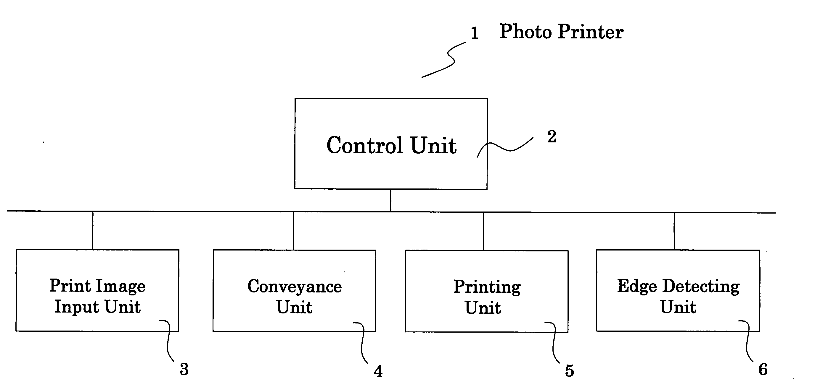
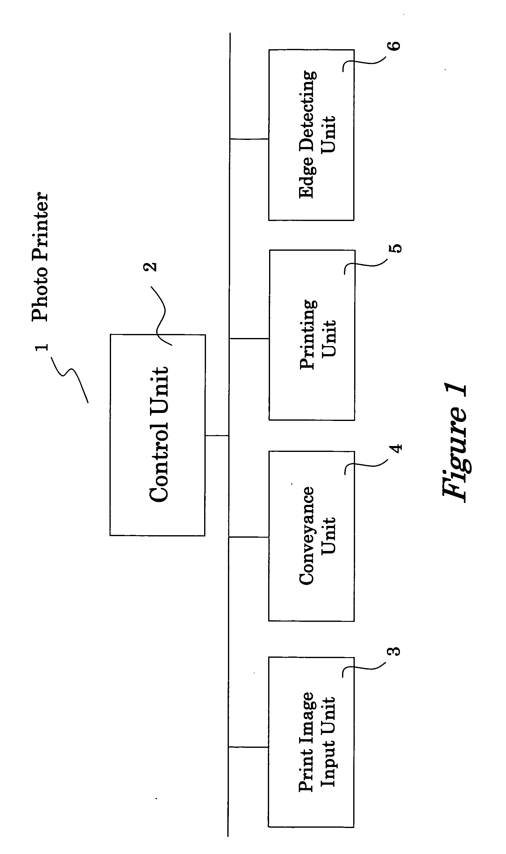
[0041]FIG. 1 is a block diagram showing the structure of a photo printer 1 in accordance with the embodiment of the present invention. The photo printer 1 has a control unit 2 for controlling the operation of various components of the photo printer 1, a print image input unit 3 for receiving an input of color images to be printed, a conveyance unit 4 which conveys the roll paper that is mounted on the printer along a conveyance path, a printing unit 5 for printin...


PUM


Abstract

The photo printer has a conveyance unit, a printing unit, line sensors and a control unit. The conveyance unit conveys a roll paper along a conveyance path. The printing unit has a thermal head that prints images on the roll paper in a main scanning direction, which is perpendicular to the conveyance direction of the roll paper. The line sensors have a plurality of light emitting elements and light receiving elements disposed so as to span side edges of the conveyance path. The line sensors detect the roll paper on the conveyance path based on an amount of light received by the light receiving elements. The control unit detects a side edge of the roll paper, and also determines that a distal end of the roll paper is detected, based on the amount of light received by the light receiving elements.

Description

BACKGROUND OF THE INVENTION [0001] 1. Field of the Invention [0002] The present invention relates to a photo printer for printing color images on roll paper, the roll paper being provided with yellow, magenta, and cyan heat-sensitive coloring layers. [0003] 2. Background Information [0004] There are photo printers for printing color images on roll paper that is provided with yellow, magenta, and cyan heat-sensitive coloring layers. The following steps (1) to (5) are generally involved in printing color images. [0005] (1) The heat sensitivity temperature for the thermal head is set to a first level, which is a temperature at which the yellow heat-sensitive coloring layer becomes colored, but the magenta and cyan heat-sensitive coloring layers do not become colored. This way, images in yellow are printed on the yellow heat-sensitive coloring layer in a printing region of the roll paper on which the current color image is to be printed. [0006] (2) The yellow images printed in step (1) ...

Claims


Application Information

Patent Timeline
Patent Type & Authority Applications(United States)
IPC IPC(8): B41J2/32B41J11/42B41J11/00B41J15/04B41J29/393B65H26/00
CPCB41J15/04B41J11/0095
Inventor UEDA, HIDEO
Owner FUNAI ELECTRIC CO LTD
Why Eureka
Try Eureka