Method for transmitting/receiving signal in MIMO system

a technology of mobile communication system and transmitting signal, which is applied in diversity/multi-antenna system, multiplex communication, channel coding adaptation, etc., can solve the problems of difficult application of methods, difficult to apply, and difficulty for the receiving end, so as to improve data transmission speed and a receiving rate

Inactive Publication Date: 2005-07-21
LG ELECTRONICS INC
View PDF7 Cites 144 Cited by
  • Summary
  • Abstract
  • Description
  • Claims
  • Application Information

AI Technical Summary

Benefits of technology

[0031] Therefore, an object of the present invention is to provide a method for transmitting a signal capable of improving data transmission speed and a receiving rate in a D-STTD system and a system with which beamforming is combined.

Problems solved by technology

However, in case of using this method, it is very difficult for the receiving end to obtain the correlation between the transmit antennas, and accordingly the method may also be actually difficult to be applied.
However, this method for transmitting a signal is a signal processing method adopted only in case of using two transmit antennas, so that it is hard to be applied as it is when using more than two transmit antennas.
However, obtaining the value of the correlation matrix of the transmitting end is actually very difficult, so that the STTD combined with the beamforming of the related art can not be easily applied.
The method for obtaining the weight value by using the correlation value between the transmit antennas of the related art may thus be hard to be actually applied.
As a result, it is not an actually proper method for application.

Method used


Image

  • Method for transmitting/receiving signal in MIMO system
  • Method for transmitting/receiving signal in MIMO system
  • Method for transmitting/receiving signal in MIMO system

Examples


Embodiment Construction

[0054] Reference will now be made in detail to the preferred embodiments of the present invention, examples of which are illustrated in the accompanying drawings.

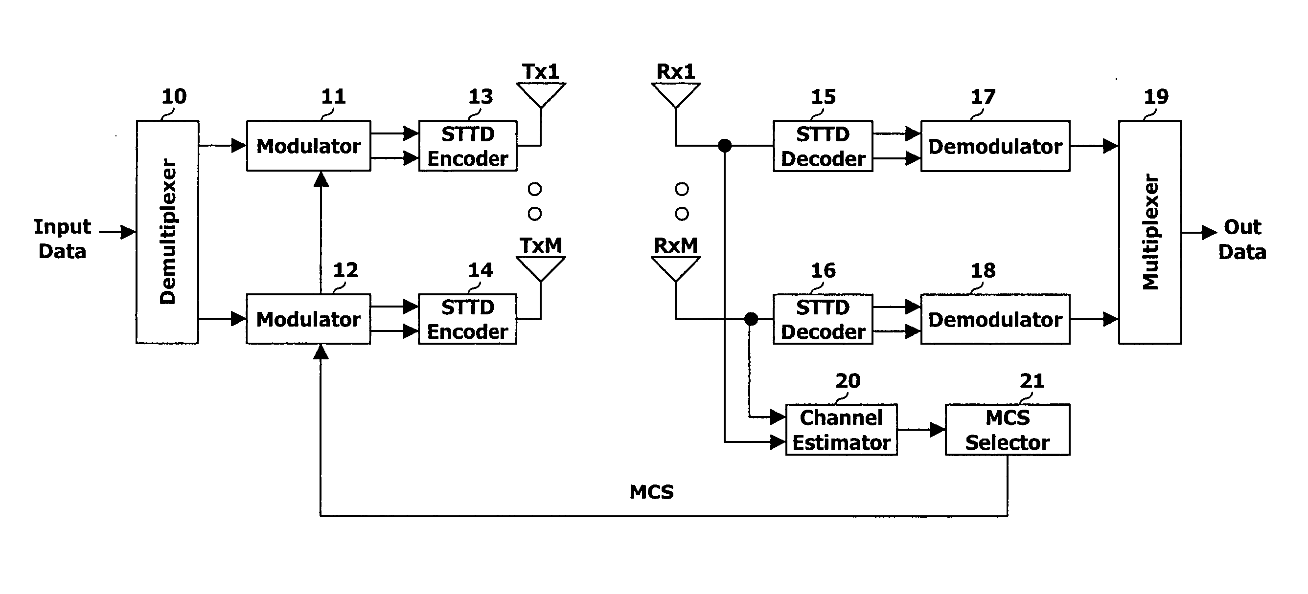
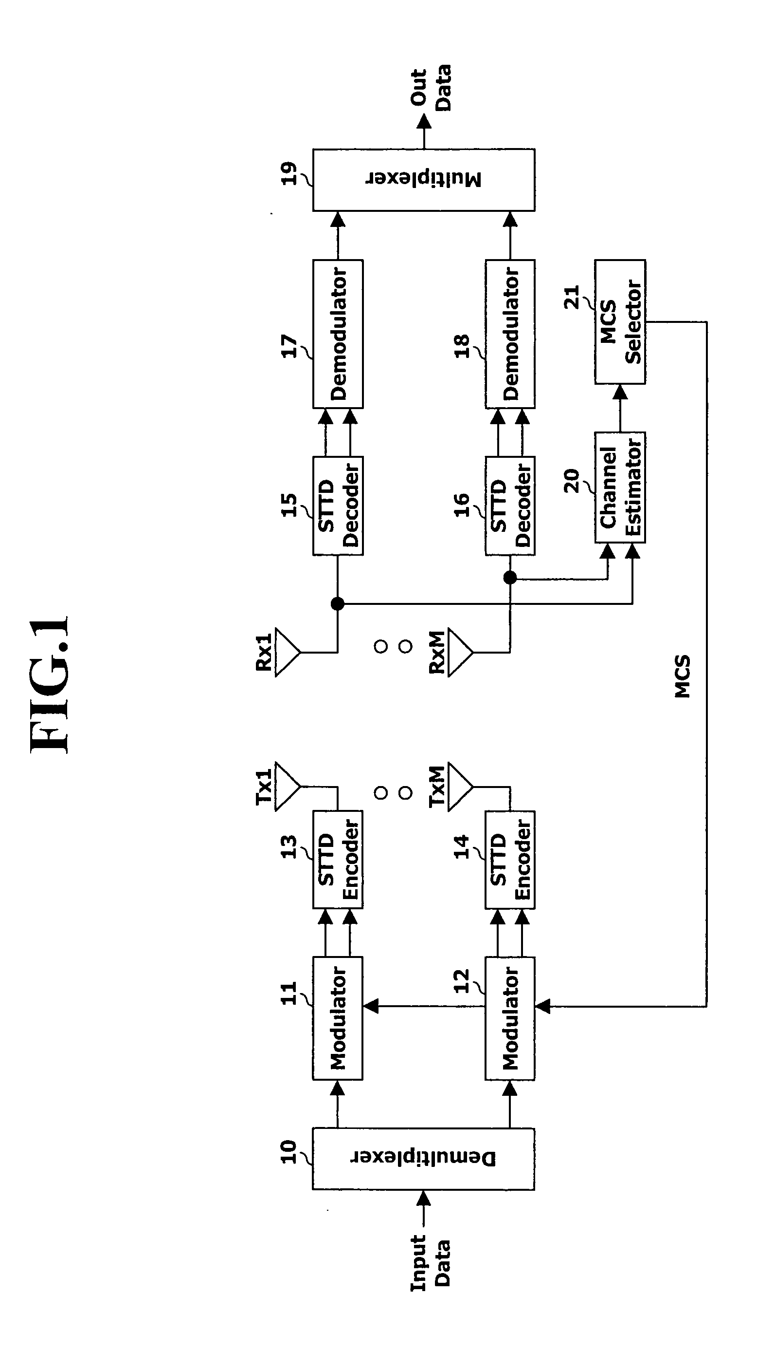
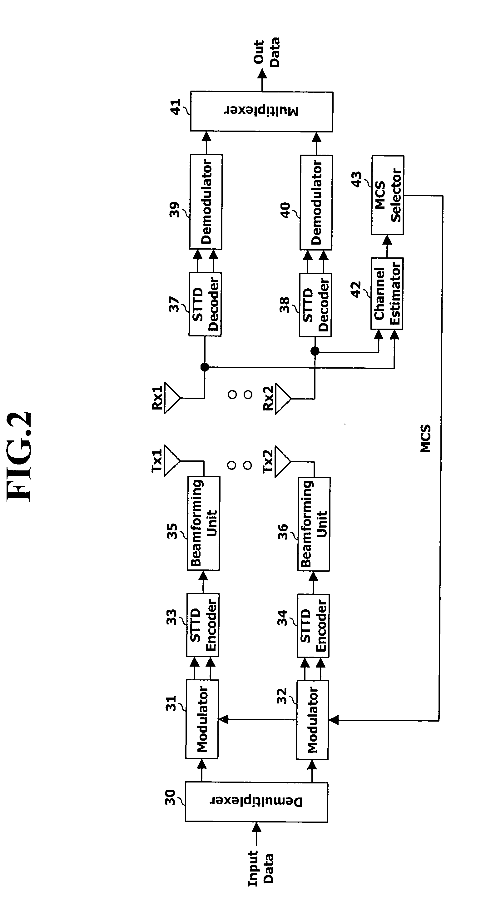
[0055] There is proposed a method for transmitting a signal in a mobile communications system using a plurality of transmit antennas and receive antennas, for instance, a D-STTD system, an STTD system with which a beamforming is combined, or the like. For this purpose, a transmitting end having a plurality of transmit antennas receives from a receiving end MCS information, determination information of an STTD pair (an antenna pair) and / or an eigenvector by a feedback signal, and accordingly performs a D-STTD transmission or a beamforming.

[0056] Preferably, the feedback signal may be predetermined by an agreement between transmitting and receiving ends. Also, the MCS information to be used in the determined antenna pair is transmitted by using separate feedback information. The MCS information should be predetermined at th...


PUM


Abstract

Disclosed is a method for transmitting a signal in a mobile communications system using a plurality of transmit/receive antennas. A method for transmitting a signal in accordance with an embodiment of the present invention comprises the steps of: a receiving end's calculating a signal to interference noise ratio (SINR) with respect to every antenna pairs configuring STTD pairs to be transmittable from a transmitting end; feedbacking information indicating an antenna pair having the greatest SINR to the transmitting end; and the transmitting end's performing a D-STTD transmission through the antenna pair determined by the feedbacked information. A method for transmitting a signal in accordance with another embodiment of the present invention comprises the steps of: a receiving end's feedbacking information of an antenna pair and/or an eigenvector (weight vector) of a channel matrix with respect to transmit antennas included in the space-time multiplexing (STTD) pair to a transmitting end; and the transmitting end's forming beam by multiplying a symbol with respect to each STTD pair by the eigenvector, and thereafter transmitting the beam through each transmit antenna (in case of using two antennas) or a transmit antenna pair (in case of using more than four antennas) determined by the information of the antenna pair.

Description

BACKGROUND OF THE INVENTION [0001] 1. Field of the Invention [0002] The present invention relates to a method for transmitting a signal in a mobile communications system, and particularly, to a method for transmitting a signal in an MIMO system using a plurality of transmit / receive antennas. [0003] 2. Background of the Related Art [0004] Recently, IMT-2000 system based on a third generation partnership project (3GPP) of W-CDMA wireless specification has adopted a space time transmit diversity (STTD) as an open loop type transmit diversity technique. The STTD refers to a technique for achieving a diversity advantage through a space-time coding extending a channel coding usually applied in a time base to a space based. [0005] The STTD can be applied to every downlink physical channels except a synchronization channel (SCH) of WCDMA, in which there is no need for feedback information transmitted from a receiving end to a transmitting end, and accordingly it is advantageous to have dive...

Claims


Application Information

Patent Timeline
Patent Type & Authority Applications(United States)
IPC IPC(8): H04J99/00H04B7/02H04B7/04H04B7/06H04L1/00H04L1/02H04L1/06
CPCH04B7/0413H04B7/0417H04B7/0615H04B7/0617H04B7/0634H04B7/0669H04L1/0675H04B7/0673H04B7/0691H04B7/0697H04L1/0003H04L1/0009H04L1/0625H04B7/0671
Inventor SHIM, DONG-HEELEE, HEE-JOUNGHUH, KANG-SUK
Owner LG ELECTRONICS INC
Why Eureka
Try Eureka