Lightweight container and method of manufacture

a technology of light weight containers and manufacturing methods, applied in the direction of transportation and packaging, other domestic articles, synthetic resin layered products, etc., can solve the problems of limiting the cycle time of molding process, limiting the thickness of the wall and forming the finish limits the thickness of the preform body. to achieve the effect of more accurate and stable dimensioning

Inactive Publication Date: 2005-07-21
GRAHAM PACKAGING PET TECH
View PDF13 Cites 27 Cited by
  • Summary
  • Abstract
  • Description
  • Claims
  • Application Information

AI Technical Summary

Benefits of technology

[0002] In the manufacture of plastic containers, it is conventional to injection mold or compression mold a container preform having a body and a finish with one or more external threads. The preform finish typically is molded to its final geometry, while the body of the preform subsequently is blow molded to the desired geometry of the container body. The preform may be of monolayer construction, or may be of multilayer construction in which one or more intermediate layers in the preform body may or may not extend into the finish area of the preform. U.S. Pat. Nos. 4,609,516, 4,710,118 and 4,954,376 illustrate injection molding of multilayer container preforms.
[0003] Molding the finish portion of the container as part of the preform presents a number of problems. For example, when the preforms are formed by injection molding, the plastic material typically is injected into a mold cavity at the closed end of the preform body, so that the material must flow along the sides of the preform cavity into the area in which the finish is molded. The finish typically requires more accurate and stable dimensioning than the body of the preform, which may limit the cycle time of the molding process. Furthermore, the difficulty in forming the finish limits how thin the wall of the preform body can be. By the time a thick preform finish fills, the sidewall of the preform body can begin to cool if it is too thin. If the finish is made thin to limit the amount of time needed to fill the finish, the finish may not fill fully, and may not have the desired strength for securement of a container closure. It is a general object of the present invention to provide a method of making container preforms and containers, a preform and a container that address

Problems solved by technology

Molding the finish portion of the container as part of the preform presents a number of problems.
The finish typically requires more accurate and stable dimensioning than the body of the preform, which may limit the cycle time of the molding process.
Furthermore, the diff

Method used


Image

  • Lightweight container and method of manufacture
  • Lightweight container and method of manufacture

Examples


Embodiment Construction

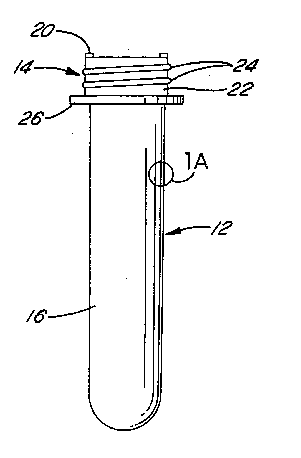
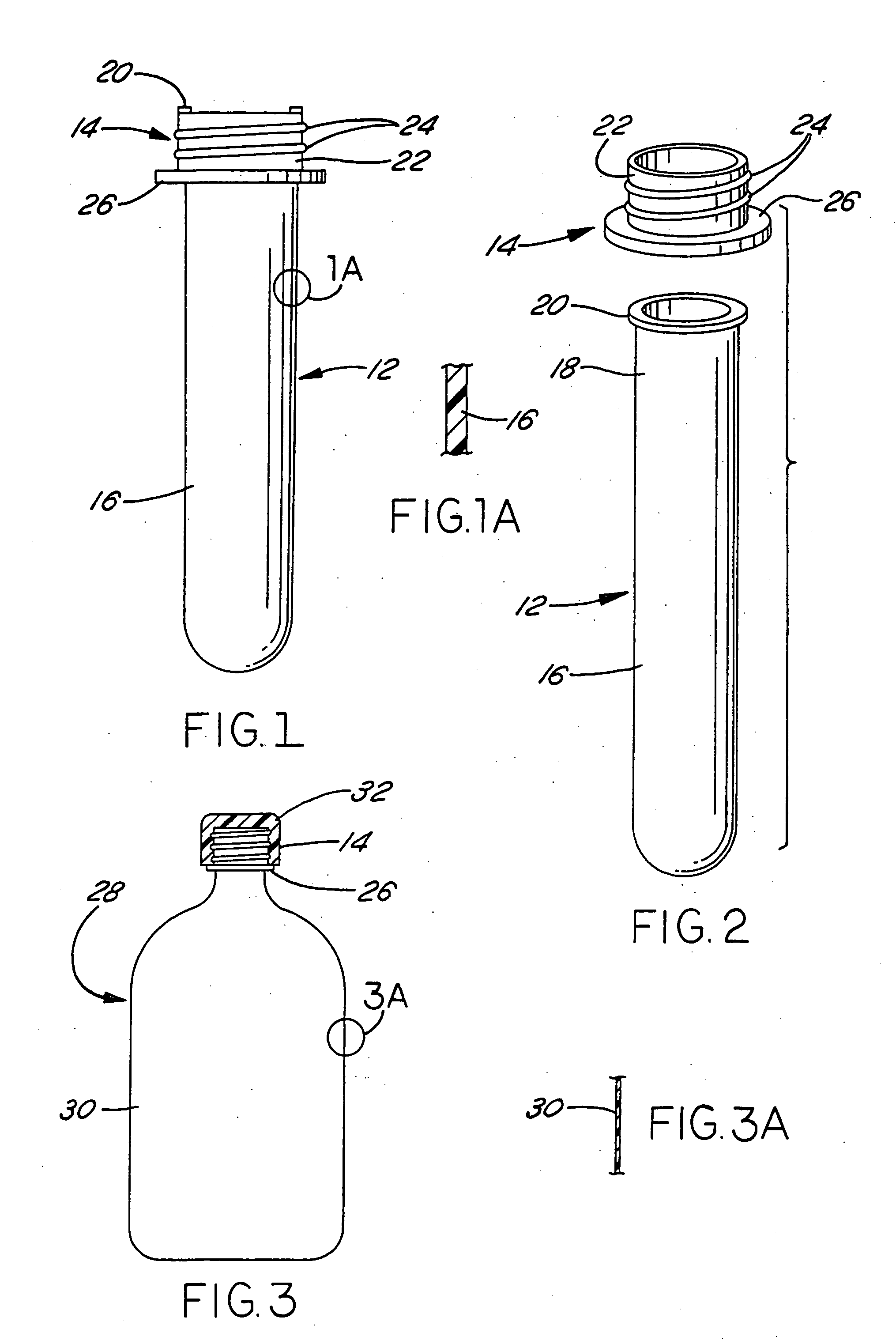
[0013]FIGS. 1-2 illustrate a preform assembly 10 in accordance with one exemplary aspect of the invention as comprising a preform 12 and a separate finish ring 14 externally secured to the neck of preform 12. Preform 12 includes a body 16 having a closed lower end and a neck 18 integrally molded with body 16. (Directional words such as “upper” and “lower” are employed by way of description and not limitation with respect to the upright orientation of the preform assembly, container and package illustrated in the drawings. Directional words such as “radial” and “circumferential” are employed by way of description and not limitation with respect to the axis of the preform neck or finish ring as appropriate.) Neck 18 typically is cylindrical. A flange 20 preferably extends radially outwardly from the open end of neck 18 remote from body 16. Neck 18 and flange 20 surround the open mouth of preform 12.

[0014] Finish ring 14 may be circumferentially continuous or circumferentially split t...


PUM

PropertyMeasurementUnit
Temperatureaaaaaaaaaa
Lengthaaaaaaaaaa
Lengthaaaaaaaaaa

Abstract

A hollow plastic container includes an open finish, a closed bottom and a sidewall connecting the finish to the bottom. The sidewall is ultra thin, having a radial wall thickness of not more than 0.008 inch, preferably in the range of about 0.003 to 0.004 inch. The container preferably is blow molded from a preform having a wall thickness such that a stretch ratio of eight to ten is obtained during the blowing operation. The preform may be heated prior to blow molding to achieve sidewall crystallization at a level of 28% to 35%.

Description

[0001] The present invention relates to blow molded plastic containers, to preforms for blow molding such containers, and to methods of making such preforms and containers. BACKGROUND AND SUMMARY OF THE INVENTION [0002] In the manufacture of plastic containers, it is conventional to injection mold or compression mold a container preform having a body and a finish with one or more external threads. The preform finish typically is molded to its final geometry, while the body of the preform subsequently is blow molded to the desired geometry of the container body. The preform may be of monolayer construction, or may be of multilayer construction in which one or more intermediate layers in the preform body may or may not extend into the finish area of the preform. U.S. Pat. Nos. 4,609,516, 4,710,118 and 4,954,376 illustrate injection molding of multilayer container preforms. [0003] Molding the finish portion of the container as part of the preform presents a number of problems. For exam...

Claims


Application Information

Patent Timeline
IPC IPC(8): B29C49/00B29C49/02B29C49/06B29C65/08B29C65/48B65D1/02
CPCB29B2911/1402Y10T428/1352B29B2911/14033B29B2911/1404B29B2911/14053B29B2911/14066B29B2911/1408B29B2911/14093B29B2911/14106B29B2911/14113B29B2911/14133B29B2911/1414B29B2911/14213B29B2911/1422B29B2911/14326B29B2911/14333B29B2911/1444B29B2911/1458B29B2911/14593B29B2911/14926B29C49/0005B29C49/0073B29C49/02B29C49/06B29C65/08B29C65/48B29C2049/021B29C2049/2026B29K2023/06B29K2023/12B29K2067/00B29K2995/004B29K2995/0041B29K2995/0043B65D1/023B29B2911/1442B29C66/5344B29C66/542B29B2911/14026B29C2949/3008B29C2949/3012B29C2949/3026B29C2949/3016B29C2949/302B29C2949/3024B29C2949/3034B29C2949/26B29C2949/28B29C2949/24B29C2949/22B29C2949/3032B29C2949/3058B29C2949/3056B29C2949/077B29C2949/073B29C2949/072B29C2949/0811B29C2949/0801B29C2949/0773B29C2949/0865B29C2949/08B29C49/071B29C2949/0715B29C49/6605B29C49/087B29C2049/7879
Inventor NAHILL, THOMAS E.
Owner GRAHAM PACKAGING PET TECH
Why Eureka
Try Eureka