Numerical control device

ontrol device technology, applied in the direction of program control, electric programme control, instruments, etc., can solve the problems of complicated programs and the like, long cycle time for executing synchronous control, complicating and lengthening the control to be performed etc., to facilitate the execution simplifying the program and the like, and reducing the cycle time of synchronous control by a numerical control device

Inactive Publication Date: 2005-02-03
FANUC LTD
View PDF10 Cites 13 Cited by
  • Summary
  • Abstract
  • Description
  • Claims
  • Application Information

AI Technical Summary

Benefits of technology

[0027] In accordance with the present invention, the programs, parameters, signals and other commands for causing a numerical control device to execute synchronous control are simplified, thus facilitating the control by the numerical control device. Furthermore, the cycle time of the synchronous control by the numerical control device can be shortened.

Problems solved by technology

Therefore, in the programs, parameters, signals and the like, it is necessary to state commands for deciding the relationships among these axes, causing problems in that the programs and the like become complicated, and the cycle time for executing a synchronous control becomes long.
Furthermore, even in the case where settings for each of the axes are changed, such as the case where a master axis command system is changed, it is still necessary to change the programs, parameters, signals and the like, thus complicating and lengthening the controls to be performed by a numerical control device.

Method used


Image

  • Numerical control device
  • Numerical control device
  • Numerical control device

Examples


first embodiment

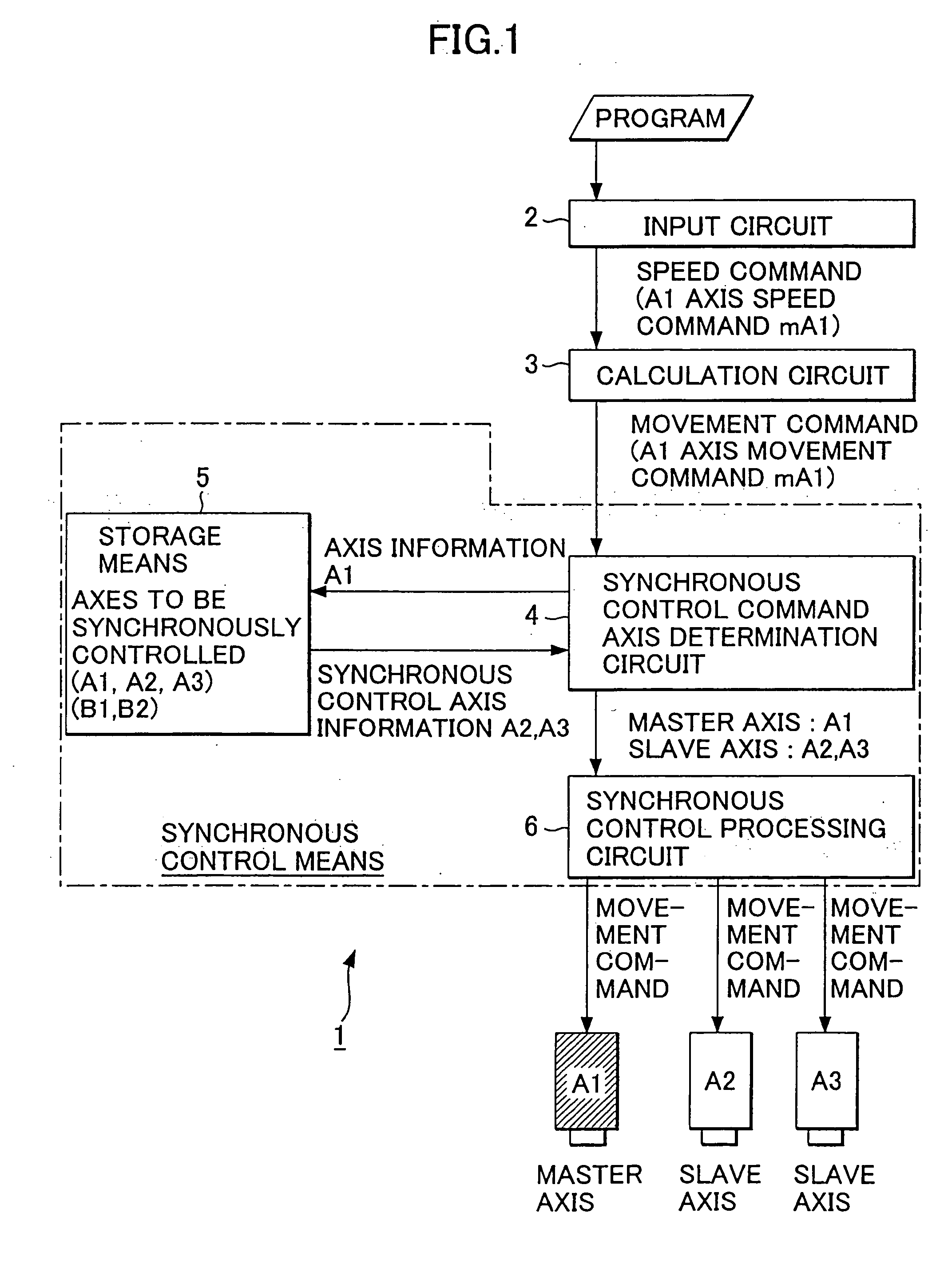
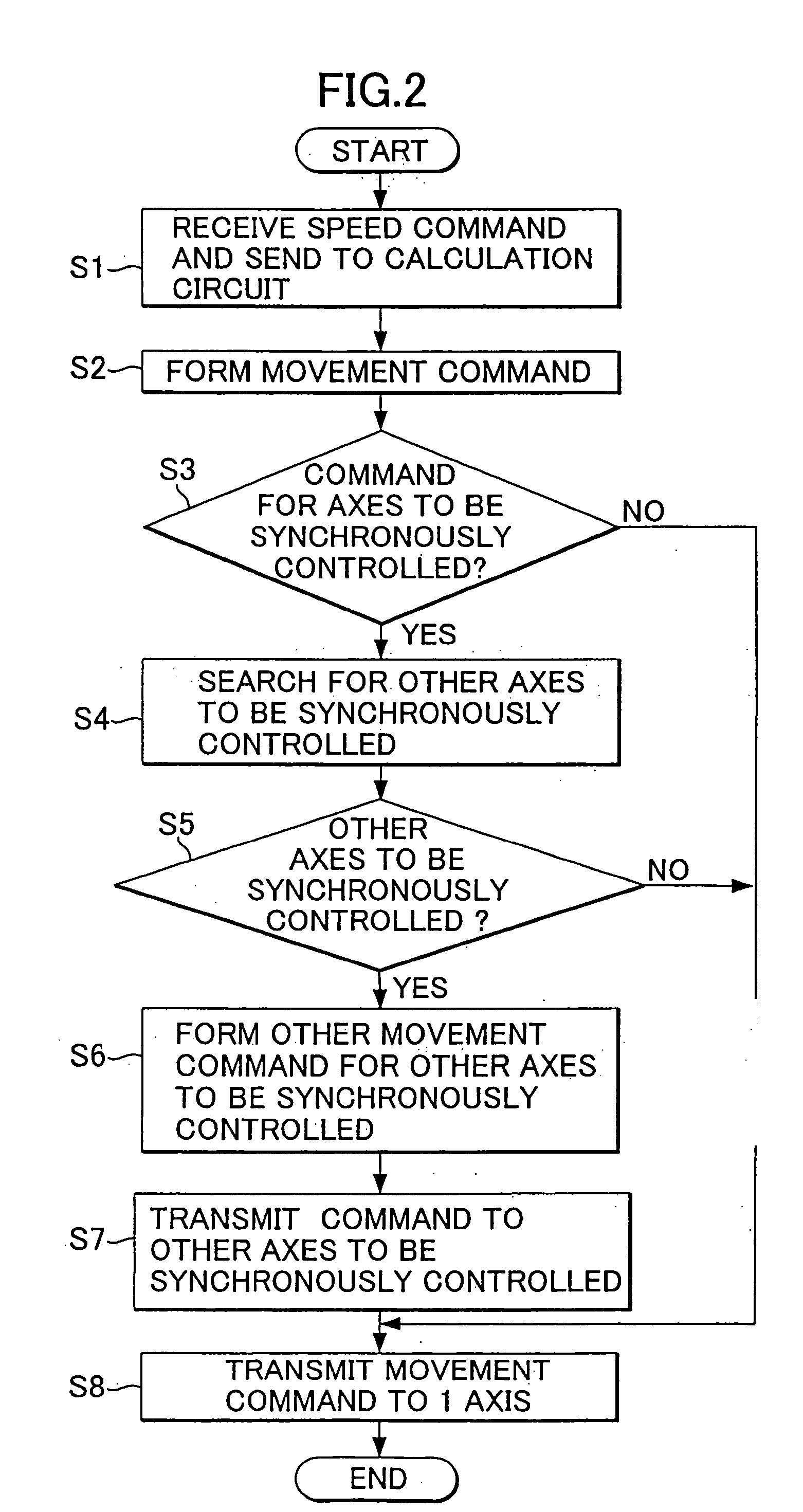
[0041] First, a numerical control device according to the present invention is explained with reference to FIG. 1 and FIG. 2. FIG. 1 shows only the components relating to synchronous control, among the components a numerical control device comprises, and other components are omitted from the drawing.

[0042] According to this first embodiment, a speed command is given to one axis among a plurality of axes to be synchronously controlled, and the synchronous control is performed based on this speed command.

[0043] A numerical control device 1 is provided with an input circuit 2, a calculation circuit 3, a synchronous control command axis determination circuit 4, storage means 5, and a synchronous control processing circuit 6. The synchronous control command axis determination circuit 4, the storage means 5 and the synchronous control processing circuit 6 constitute synchronous control means, which synchronously control a plurality of axes (A1, A2, A3). Here, as the axes to be synchronou...

second embodiment

[0057] Next, a numerical control device according to the present invention is explained with reference to FIG. 3 and FIG. 4. FIG. 3 shows only the components relating to synchronous control, among the components a numerical control device comprises, and other components are omitted from the drawing.

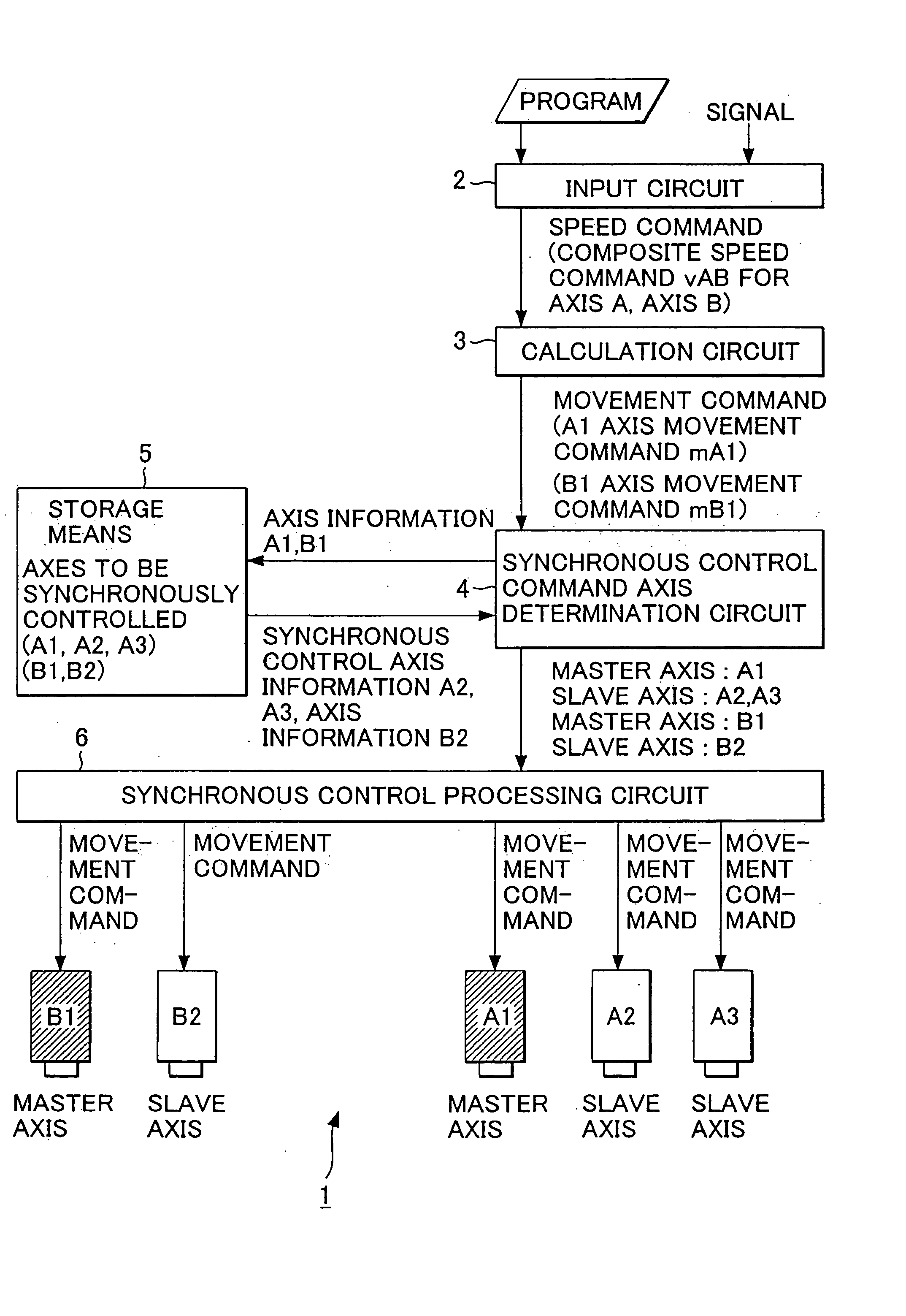
[0058] According to the second embodiment, a composite speed command is given to a plurality of axes to be synchronously controlled for executing a synchronous control.

[0059] The numerical control device 1 of the present embodiment has a structure similar to that of the first embodiment, including synchronous control command axis determination circuit 4, storage means 5 and synchronous control processing circuit 6, which constitute synchronous control means for synchronously controlling a plurality of axes (A1, A2, A3), (B1, B2). Axes A1, A2, A3 and axes B1 and axis B2 are shown here as axes to be synchronously controlled, however, axes to be synchronously controlled are not restricted t...

third embodiment

[0071] Next, a numerical control device according to the present invention is explained with reference to FIG. 5 and FIG. 6. FIG. 5 shows only the components relating to synchronous control, among the components a numerical control device comprises, and other components are omitted from the drawing.

[0072] According to the third embodiment, a synchronous control command axis switching circuit 7 is added to the configuration of the first embodiment, thereby switching the axis for which movement command is to be given in the course of synchronous control. In the example shown in FIG. 5, the synchronous control command axis switching circuit 7 is provided between the synchronous control command axis determination circuit 4 and the synchronous control processing circuit 6. The synchronous control command axis determination circuit 4, the storage means 5, the synchronous control processing circuit 6 and the synchronous control command axis switching circuit 7 constitute the synchronous co...


PUM


Abstract

A numerical control device is provided with a synchronous control unit that moves a slave axis in synchronization with a master axis, based on a movement command given to the master axis. The synchronous control unit is provided with a synchronous control object setting unit that determines a plurality of axes as objects of synchronous control, a synchronous control processing unit that gives movement commands to the plurality of axes to be synchronized/controlled, and a synchronous control command axis determination unit that sets one axis for which a movement command is given as a master axis in the synchronous control in association with the movement command, and sets the axes other than the master axis among the plurality of axes to be synchronously controlled as slave axes.

Description

BACKGROUND OF THE INVENTION [0001] 1. Field of the Invention [0002] The present invention relates to a numerical control device, and more particularly to a numerical control device for synchronously controlling a plurality of axes. [0003] 2. Description of the Related Art [0004] When performing axis control by means of a numerical control device, there are cases where synchronous control is executed on a plurality of axes in rotating machines, packaging machines, painting machines and the like (see, for example, Japanese patent Application Laid-Open No, 2001-27904 A). [0005]FIG. 11 is a conceptual diagram for explaining an outline of synchronous control to be executed by a conventional numerical control device. [0006] In synchronous control where an axis is synchronized to another axis, a master axis (base axis) and slave axes (synchronized axes) are set, the master axis is controlled, and the control of the slave axes is synchronized with the control performed on the master axis. I...

Claims


Application Information

Patent Timeline
Patent Type & Authority Applications(United States)
IPC IPC(8): G05B19/18G05B19/19B23Q15/00H02P1/46
CPCG05B2219/50216G05B19/19
Inventor KOCHIYA, HIDESHIENDO, TAKAHIKO
Owner FANUC LTD
Why Eureka
Try Eureka