Container preform assembly and method of manufacture

a technology of preform and container, which is applied in the direction of transportation and packaging, other domestic articles, synthetic resin layered products, etc., can solve the problems of limiting the cycle time of the molding process, limiting the ability to obtain the most desirable characteristics at the finish, and limiting the design capabilities of preform manufacture, so as to improve the operating characteristics of the finish area and improve the accuracy and stability of dimensioning

Inactive Publication Date: 2005-12-20
GRAHAM PACKAGING PET TECH
View PDF12 Cites 31 Cited by
  • Summary
  • Abstract
  • Description
  • Claims
  • Application Information

AI Technical Summary

Benefits of technology

[0002]In the manufacture of plastic containers, it is conventional to injection mold or compression mold a container preform having a body and a finish with one or more external threads. The finish typically is molded to its final geometry, while the body of the preform is subsequently blow molded to the desired geometry of the container body. The preform may be of monolayer construction, or may be of multilayer construction in which one or more intermediate layers in the preform body may or may not extend into the finish area of the preform. U.S. Pat. Nos. 4,609,516, 4,710,118 and 4,954,376 illustrate injection molding of multilayer container preforms.
[0003]Molding the finish portion of the container as part of the preform presents a number of problems. For example, when the preforms are formed by injection molding, the plastic material typically is injected into a mold cavity at the closed end of the preform body, so that the material must flow along the sides of the preform cavity into the area in which the finish is molded. The finish typically requires more accurate and stable dimensioning than the body of the preform, which may limit the cycle time of the molding process. Furthermore, the finish portion of the preform is of the same material as at least the outer layers of the preform body, which limits the ability to obtain the most desirable characteristics at the finish. When the preform is of polyester construction, such as polyethylene terephthalate (PET), the finish portion of the preform can be wholly or partially crystallized to improve the operating characteristics of the finish area, particularly in hot-fill container applications. However, the requirement that the finish be of the same material as at least the outer layers of the preform body still limits the design capabilities of preform manufacture.
[0004]A preform assembly for blow molding a container in accordance with a first aspect of the present invention includes a molded plastic preform having a body and a neck with an external surface. At least one circumferential channel is molded into the external surface of the preform neck for removing the preform from the forming mold. A plastic finish ring separate from the preform is externally secured to the preform neck over the external surface of the neck. A method of making a preform assembly for blow molding a container in accordance with a second aspect of the invention includes molding a preform having a body and a cylindrical neck with an external surface, and at least one circumferential channel molded into the external surface of the neck. A plastic finish ring is secured over the external surface of the cylindrical neck.

Problems solved by technology

Molding the finish portion of the container as part of the preform presents a number of problems.
The finish typically requires more accurate and stable dimensioning than the body of the preform, which may limit the cycle time of the molding process.
Furthermore, the finish portion of the preform is of the same material as at least the outer layers of the preform body, which limits the ability to obtain the most desirable characteristics at the finish.
However, the requirement that the finish be of the same material as at least the outer layers of the preform body still limits the design capabilities of preform manufacture.

Method used


Image

  • Container preform assembly and method of manufacture
  • Container preform assembly and method of manufacture
  • Container preform assembly and method of manufacture

Examples


Embodiment Construction

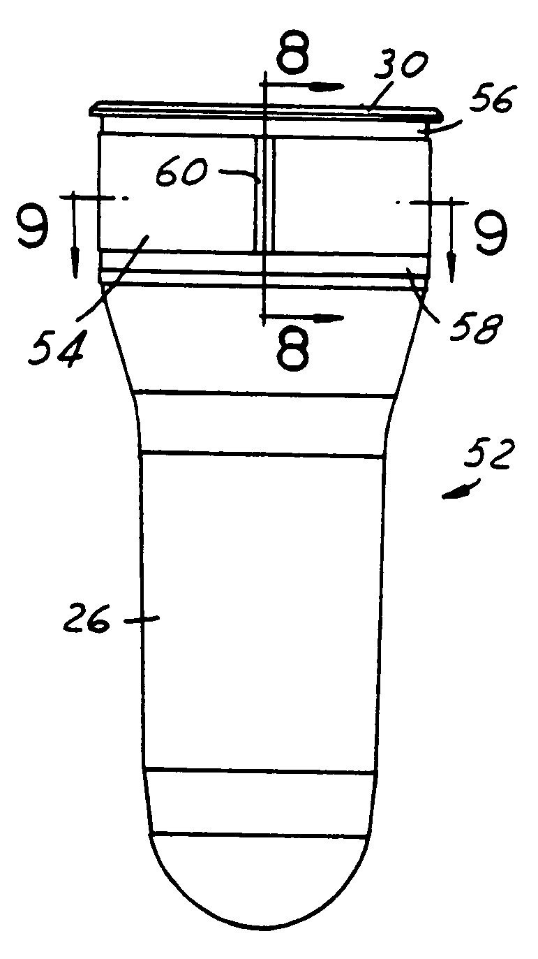
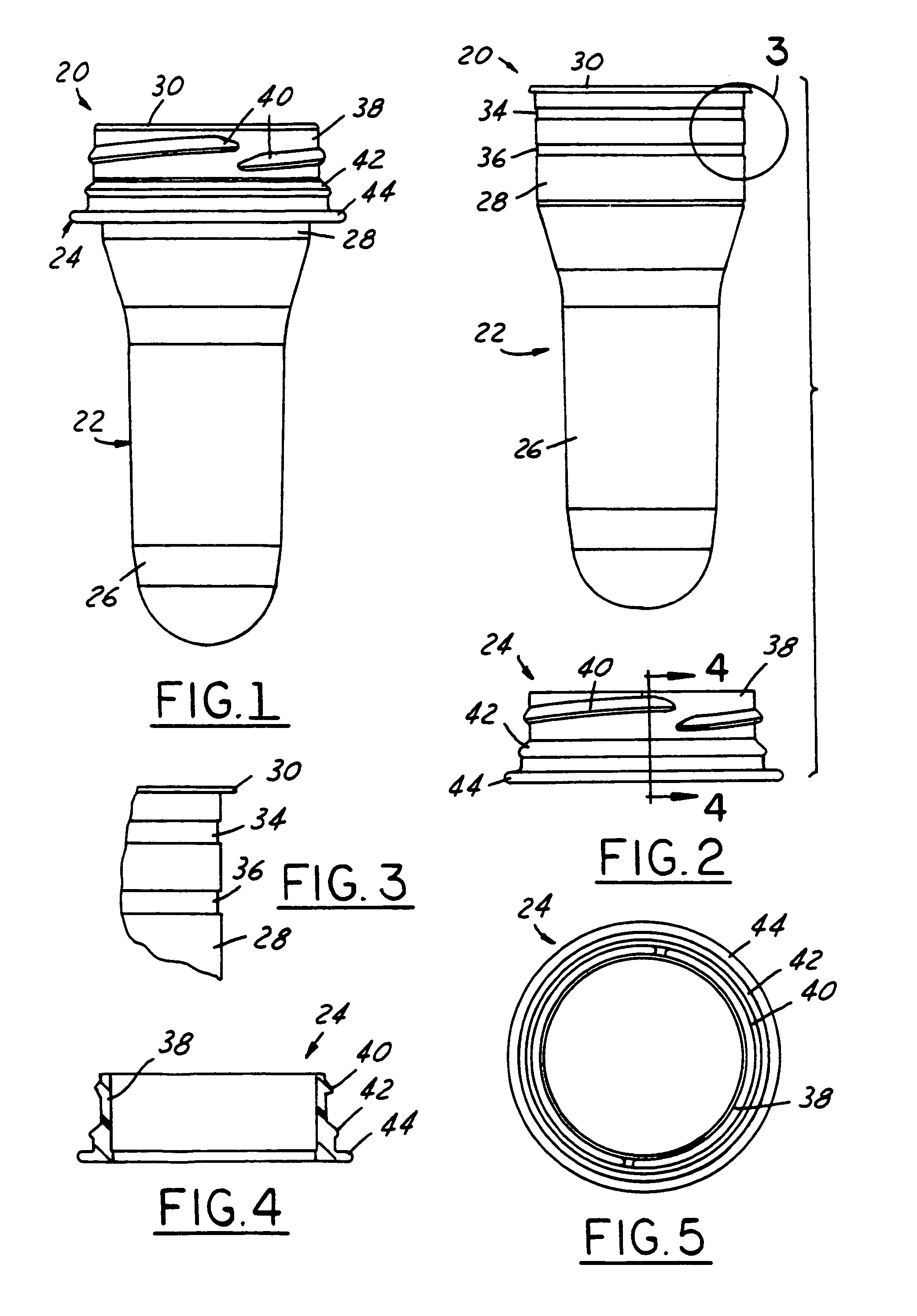
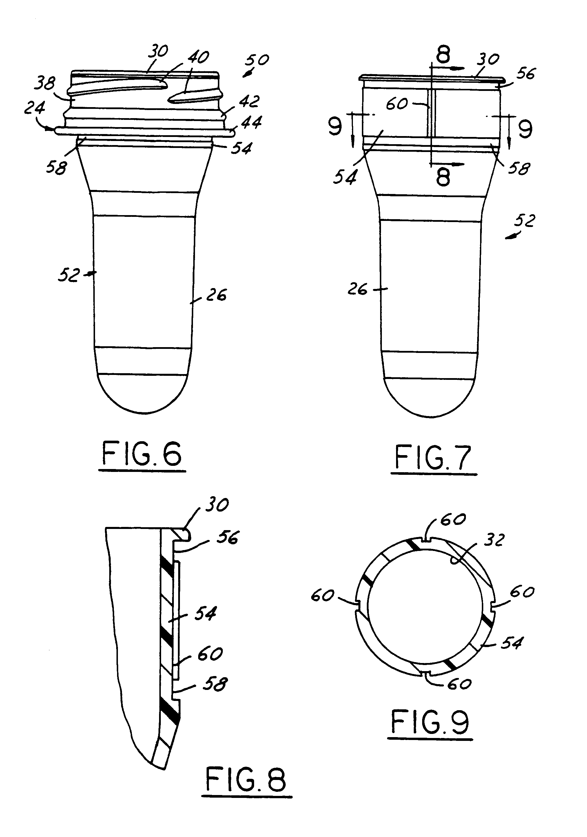
[0014]FIGS. 1–5 illustrate a preform assembly 20 in accordance with one presently preferred embodiment of the invention as comprising a preform 22 and a separate finish ring 24 secured over the neck of preform 22. Preform 22 includes a body 26 having a closed lower end, and a neck 28 integrally molded with body 26. (Directional words such as “upper” and “lower” are employed by way of description and not limitation with respect to the upright orientation of the preform assemblies and components illustrated in the drawings. Directional words such as “radial” and “circumferential” are employed by way of description and not limitation with respect to the axis of the preform neck or finish ring as appropriate.) Neck 28 typically is cylindrical. A flange 30 extends radially outward from the open end of neck 28 remote from body 26. Neck 28 and flange 30 surround the open mouth of preform 22. A pair of axially spaced circumferential channels 34, 36 extend around the outer surface of neck 28...


PUM

PropertyMeasurementUnit
areaaaaaaaaaaa
plasticaaaaaaaaaa
mold temperatureaaaaaaaaaa

Abstract

A preform assembly for blow molding a container includes a molded plastic preform having a body and a neck with an external surface. At least one circumferential channel is molded into the external surface of the preform neck for removing the preform from the forming mold. A plastic finish ring separate from the preform is externally secured to the preform neck over the external surface of the neck.

Description

[0001]The present invention is directed to preforms for blow molding plastic containers, and to methods of making such preforms.BACKGROUND AND SUMMARY OF THE INVENTION[0002]In the manufacture of plastic containers, it is conventional to injection mold or compression mold a container preform having a body and a finish with one or more external threads. The finish typically is molded to its final geometry, while the body of the preform is subsequently blow molded to the desired geometry of the container body. The preform may be of monolayer construction, or may be of multilayer construction in which one or more intermediate layers in the preform body may or may not extend into the finish area of the preform. U.S. Pat. Nos. 4,609,516, 4,710,118 and 4,954,376 illustrate injection molding of multilayer container preforms.[0003]Molding the finish portion of the container as part of the preform presents a number of problems. For example, when the preforms are formed by injection molding, t...

Claims


Application Information

Patent Timeline
Patent Type & Authority Patents(United States)
IPC IPC(8): B29C49/00B29C49/06B32B1/08B65B7/28B65D1/02B65D1/46
CPCB29C49/0073B29C65/00B29C66/5344B29B2911/1402Y10T428/1352B29B2911/14033B29B2911/1404B29B2911/14053B29B2911/1406B29B2911/14066B29B2911/1408B29B2911/14093B29B2911/14106B29B2911/14113B29B2911/1412B29B2911/14126B29B2911/14133B29B2911/14146B29B2911/14153B29B2911/14213B29B2911/14226B29B2911/14233B29B2911/14326B29B2911/14333B29B2911/14413B29B2911/1444B29B2911/14466B29B2911/1458B29C49/06B29C65/02B29C65/48B29C65/565B29C66/712B29C2049/021B29C2049/2017B29C2049/2026B29K2023/06B29K2023/086B29K2023/12B29K2067/00B29K2623/086B29K2995/004B29K2995/0041B29B2911/14026B29B2911/1442B29C66/73773B29C66/73921B29C66/71B29C66/1222B29C66/1224B29C66/1312B29C66/7234B29C2949/3009B29C2949/3016B29C2949/302B29C2949/3024B29C2949/28B29C2949/26B29C2949/24B29C2949/22B29C2949/3026B29C2949/3008B29C2949/3012B29C2949/303B29C2949/3028B29C2949/3036B29C2949/3038B29C2949/3062B29C2949/306B29C2949/3056B29C2949/3032B29C2949/0722B29C2949/0744B29C2949/0731B29C2949/072B29C2949/0733B29C2949/0769B29C2949/077B29C2949/0801B29C2949/073B29C2949/0777B29C2949/0773B29C2949/08B29C49/071B29C2949/079B29C2949/0715B29K2077/00B29K2067/003
Inventor NAHILL, THOMAS E.LYNCH, BRIAN A.DIPASQUALE, JEFFREY D.
Owner GRAHAM PACKAGING PET TECH
Why Eureka
Try Eureka