Recuperative reforming reactor

a technology of recuperative reforming and reactor, which is applied in the direction of machines/engines, combustion air/fuel air treatment, and combustion process, etc., can solve the problems of increasing the urgency of efforts, unable to meet the needs of engines, and unable to achieve rapid heat dissipation, etc., to facilitate the catalytic reforming reaction, facilitate the effect of recuperative reforming and high heating valu

Inactive Publication Date: 2007-02-08
UTILIZATION TECH DEV NFP
View PDF5 Cites 47 Cited by
  • Summary
  • Abstract
  • Description
  • Claims
  • Application Information

AI Technical Summary

Benefits of technology

[0018] Thus, the method and apparatus of this invention not only facilitate the catalyzed reforming reaction, but also continually provide the critically required heat into the reaction. In addition, in one single vessel having heat exchange means and reaction promoting means, the reactions can be made to continue and proceed until the recoverable amount of heat in the heat exchange fluid has been converted virtually completely into a virgin fuel (reformate fuel) in the form of a mixture of hydrogen and carbon monoxide. That is to say, a substantial portion of the heat, which in accordance with preferred embodiments of this invention is derived from the high temperature exhaust gases of internal combustion engines and industrial furnaces, is removed and converted by thermo-chemical means into high value fuel having a higher heating value than the initial hydrocarbon fuel. This high value fuel can then be injected, as a separate stream or together with the primary engine or furnace fuel into the same internal combustion engine or industrial furnace, respectively, that discharges the high temperature exhaust gases, or into another engine or industrial furnace. After injection or aspiration, the engine will readily combust this fuel. In fact, the high hydrogen content of the injected / aspirated fuel modifies the combustion process such that, in addition to a reduction in fuel consumption, the engine will exhibit better operational features such as more reliable ignition. In addition, experience has shown that combustion generated pollutants are substantially reduced compared to the combustion generated pollutants from conventionally operated engines.
[0019] A reduction in fuel consumption as may occur with the method and apparatus of this invention compared to conventional engines has several benefits. For example, operating costs relating to fuel costs are reduced while engine power output and performance remain unchanged. In addition, the method and apparatus of this invention offer the possibility of substantial additional benefits. In particular, if the same amount of power can be produced with substantially less fuel, it will be apparent that engine efficiency has increased. Thus, by adding the apparatus of this invention to an engine, it now seems possible to build a diesel engine that can break the 50% efficiency barrier.
[0020] The injection of hydrogen into the combustion reaction also has other benefits. It is theoretically and practically possible to completely bum all fuel injected into the engine. Exhaust gases from high temperature combustion processes using hydrogen as part of the fuel mixture virtually do not contain any other emissions than nitrogen, water vapor, and carbon dioxide.

Problems solved by technology

Thermal processes often reject large amounts of heat.
Since the invention of these engines, efforts have been ongoing to increase their mechanical efficiency; and as fuel costs increase, these efforts become more urgent.
A method commonly employed in boilers and other heating devices, namely preheating of combustion air by exchanging heat in a heat exchanger, is not readily applicable to engines because the mass of preheated air or gas aspirated by the engine will be much smaller and will lead to performance derating.
In addition, engine cooling will become more complex.
However, when dealing with lower temperatures, such as are encountered with exhaust gases from engines and many furnace applications, heat transfer mechanisms change drastically from those at higher temperatures, especially those occurring in packed catalyst beds with strongly endothermic reactions.
When producing large percentages of hydrogen and carbon monoxide, the reaction is endothermic; that is, the reaction consumes heat.
However, despite its apparent attractiveness, this method has not found widespread use due to a number of technical problems.
However, they will extinguish themselves quickly if no heat is supplied to keep the reaction temperatures at a high enough level to maintain the reforming reactions.

Method used


Image

  • Recuperative reforming reactor
  • Recuperative reforming reactor
  • Recuperative reforming reactor

Examples


Embodiment Construction

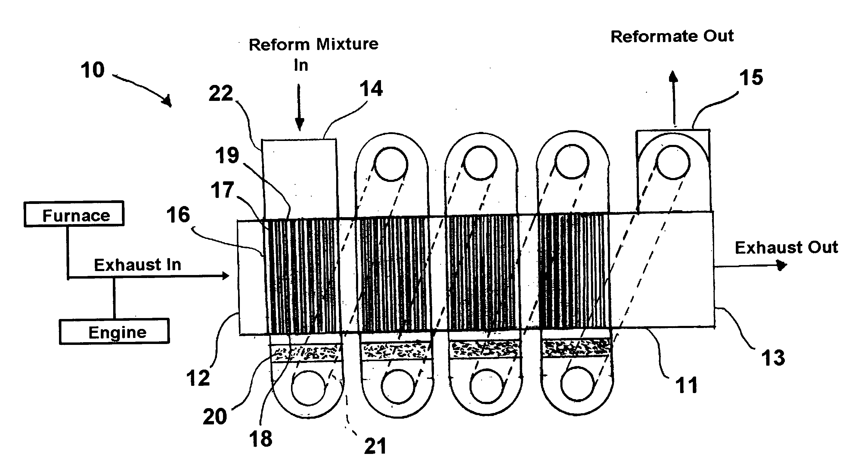
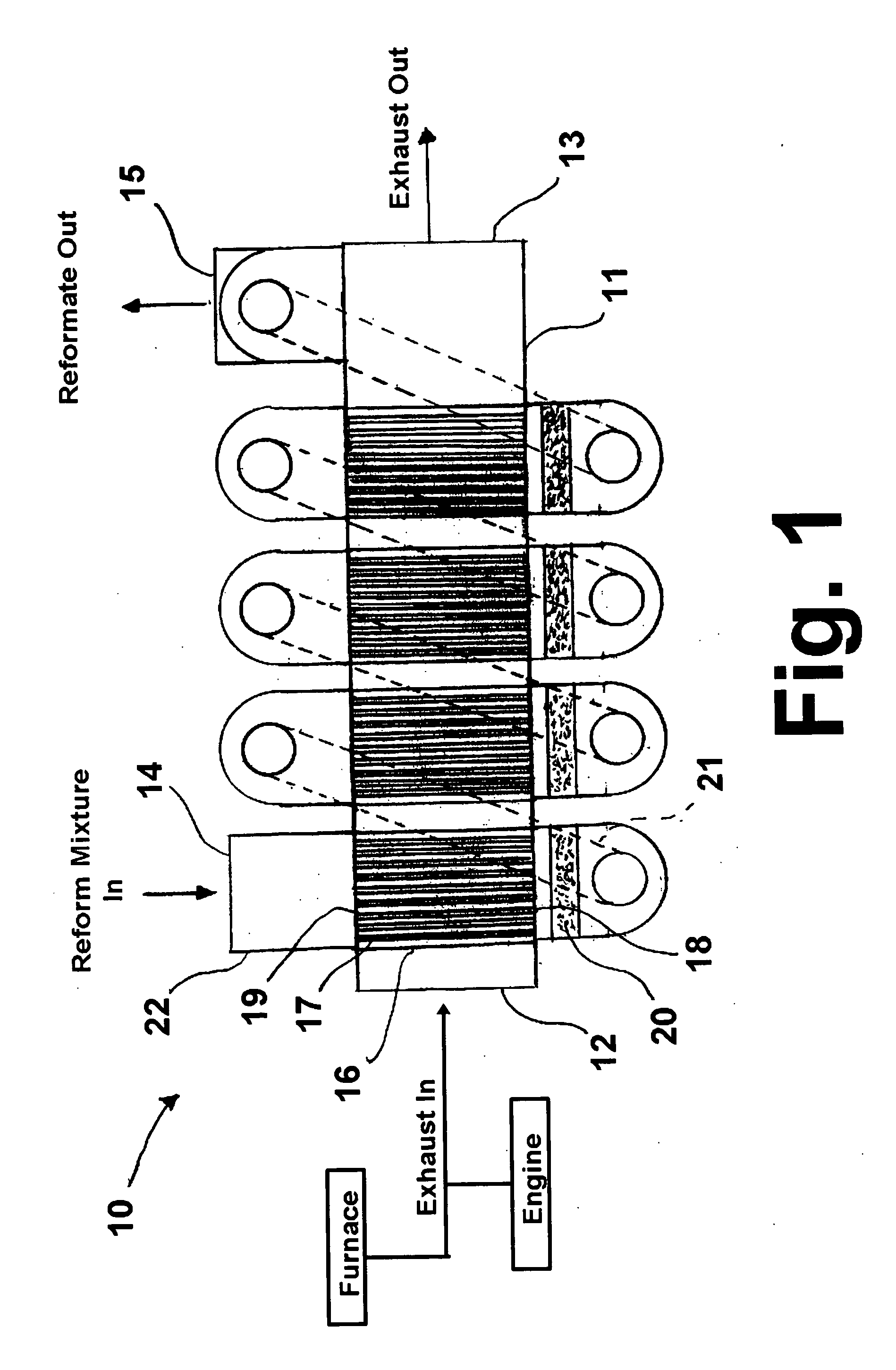
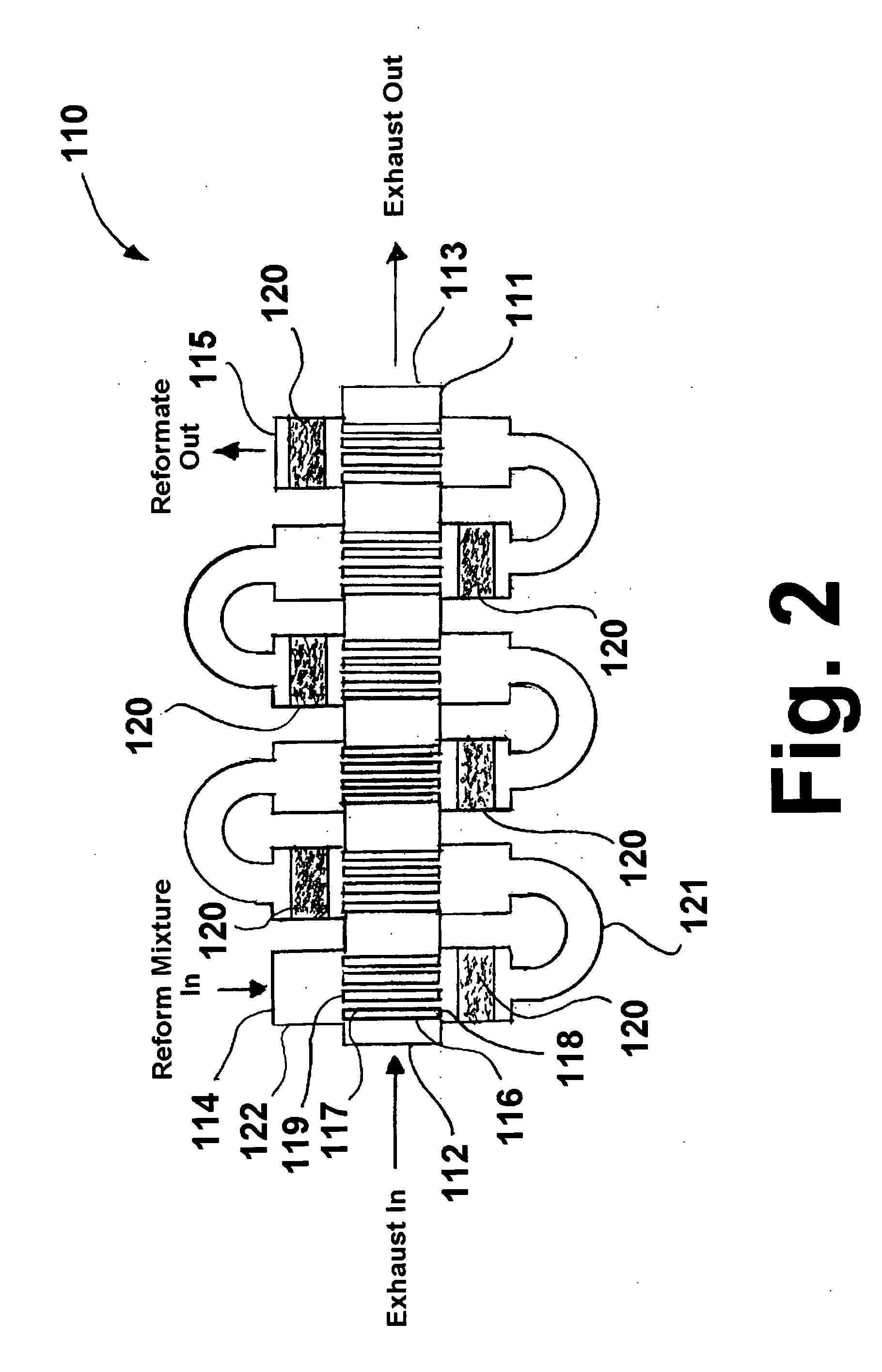
[0029] Recuperative reforming reactors in accordance with two embodiments of this invention are shown in FIGS. 1 and 2. Recuperative reforming reactor 10, 110 as shown in FIGS. 1 and 2 comprises a reforming conduit 22, 122 having a reformable fuel inlet end 14, 114 and a reformed fuel outlet end 15, 115. Reforming conduit 22, 122 comprises at least one tube bundle 16, 116 comprising a plurality of heat exchange tubes 17, 117, the tube bundle having a tube bundle inlet end 19, 119 having a reformable fuel inlet and a tube bundle outlet end 18, 118 having a reformable fuel outlet. A housing 11, 111 having a heat exchange fluid inlet 12, 112 and a heat exchange fluid outlet 13, 113 is disposed around the at least one tube bundle 16, 116 to provide a crossflow configuration of heat exchange fluid flow relative to the plurality of heat exchange tubes 17, 117 through the housing. It is to be understood that other configurations of heat exchange fluid flow relative to the plurality of heat...


PUM


Abstract

A method and apparatus for fuel reforming using the exhaust gases from internal combustion engines and high temperature combustion processes in which a fuel for reforming and steam mixture is introduced into a tube bundle having a plurality of heat exchange tubes and heat from the exhaust gases is transferred into the heat exchange tubes, thereby increasing the temperature of the mixture. The heated mixture is reformed by contact with a reforming catalyst external to, but proximate to the exit of, the tube bundle, forming a reformed fuel. To remove substantially all of the heat from the exhaust gases, a plurality of tube bundles and associated reforming catalyst arranged in series are provided.

Description

BACKGROUND OF THE INVENTION [0001] 1. Field of the Invention [0002] This invention relates to a method and apparatus for reforming hydrocarbon fuels to produce hydrogen in which extracted waste heat from internal combustion engines, furnace exhaust gases and the like at temperatures of about 1500° F. and lower and pressures ranging from a few inches of water column above atmospheric to about 10 bar is utilized to increase the temperature of a gaseous or liquid fuel, in a mixture with steam, to a level where the heated mixture will begin to react in the presence of a reforming catalyst and consume the extracted waste heat until the temperature of the catalyzed reactants becomes so low that the reaction virtually ceases. This invention may also be applied to other homogeneous or heterogeneous reactions where large amounts of reaction heats are either consumed or liberated. Without intending in any way to limit the scope of this invention, the invention as described herein is based upo...

Claims


Application Information

Patent Timeline
Patent Type & Authority Applications(United States)
IPC IPC(8): F02M27/02B01J7/00
CPCB01J8/008B01J8/0457B01J8/0496B01J8/067B01J2208/00221B01J2208/00309F02M27/02C01B3/382C01B3/384C01B2203/0233C01B2203/0811C01B2203/1294C01B2203/143B01J2219/0004
Inventor HEMSATH, KLAUS HEINRICH
Owner UTILIZATION TECH DEV NFP
Why Eureka
Try Eureka