Intraocular pressure sensor

a pressure sensor and intraocular technology, applied in the field of medical devices, can solve the problems of unsatisfactory types of devices, prior art does not teach intraocular pressure sensors having the construction and benefits, and the types of devices are also unsatisfactory

Inactive Publication Date: 2005-07-21
MONTEGRANDE VALENTINO +1
View PDF16 Cites 73 Cited by
  • Summary
  • Abstract
  • Description
  • Claims
  • Application Information

AI Technical Summary

Benefits of technology

[0024] It is another object of the present invention to provide a biosensor that does not require a physical connection, by wire or otherwise, to an external source.
[0025] It is another object of the present invention to provide a biosensor that permits non-invasive queries of conditions inside the eye of the patient.

Problems solved by technology

These types of devices are generally unsatisfactory due to increased risk of infection and patient discomfort caused by the externally extending wire.
These types of devices are also unsatisfactory for many types of medical conditions since the batteries are bulky and must be periodically replaced, thus necessitating additional surgery.
However, the prior art does not teach an intraocular pressure sensor having the construction and benefits described herein.

Method used


Image

  • Intraocular pressure sensor
  • Intraocular pressure sensor
  • Intraocular pressure sensor

Examples


first embodiment

[0058] In a first embodiment, as shown in FIG. 4, the intraocular pressure sensor 10 may be adapted to be operably installed in a contact lens 60 or similar eye 12 canopy that is adapted to be placed directly on the eye 12. The intraocular pressure sensor 10 is used in conjunction with a contact lens 60 having an inner lens surface 62 and an opposing outer lens surface 64. The inner lens surface 62 is adapted to operably contact the eye 12. The intraocular pressure sensor 10 is operably mounted on the contact lens 60 so that the pressure sensor 20 operably contacts the eye 12 when the contact lens 60 is operably placed on the eye 12.

Intraocular Lens

second embodiment

[0059] In a second embodiment, as shown in FIG. 5, the intraocular pressure sensor 10 is adapted to be operably installed on an intraocular lens 100 that is adapted to be surgically implanted into the eye 12. The intraocular lens 100 may be constructed of polymethylmethacrylate (PMMA) and may be operatively installed in the eye 12 using surgical techniques well known in the art. The pressure sensor 20 is operatively positioned on the intraocular lens 100 to enable measurement of the pressure of the eye 12.

Glaucoma Drainage Device

third embodiment

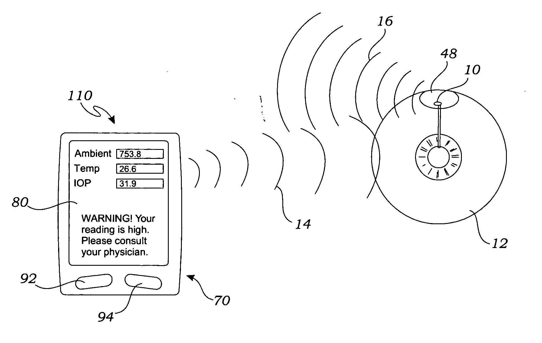
[0060] In a third embodiment, as shown in FIGS. 6-7, the intraocular pressure sensor 10 may also be adapted to be used on conjunction with a glaucoma drainage device 40. The glaucoma drainage device 40 includes a lumened tube 42 and an explant plate 48. The lumened tube 42 has a proximal end 44 and a distal end 46. The explant plate 48 has an internal surface 50 and an opposing external surface 52 that together terminate in a plate perimeter 54. The plate perimeter 54 is shaped to fit on the eye 12 and the internal surface 50 is concave to define an internal cavity 56 when the plate perimeter 54 is positioned on the eye 12. The proximal end 44 of the lumened tube 42 can be positioned through a tube aperture 58 of the explant plate 48 that is adjacent the plate perimeter 54. During surgery, the distal end 46 of the lumened tube 42 is positioned within the eye 12, to relieve pressure from within the eye 12 as directed by the doctor. The intraocular pressure sensor 10 is operable posit...


PUM


Abstract

A sensor system for sensing an intraocular pressure within an eye includes a glaucoma drainage device and a pressure sensor. The glaucoma drainage device has an explant plate and a lumened tube, the explant plate being adapted to fit over the eye, and the lumened tube being adapted to be inserted into the eye. The pressure sensor is operably attached to the glaucoma drainage device for sensing the intraocular pressure of the eye and for generating a sensor signal representative of the pressure.

Description

CROSS-REFERENCE TO RELATED APPLICATIONS [0001] This application for a utility patent is a continuation-in-part of a previously filed utility patent, now abandoned, having the application Ser. No. 10 / 452,109, filed Jun. 2, 2003. This application also claims the benefit of U.S. Provisional Application No. 60 / 384,632, filed May 31, 2002, both of which are hereby incorporated by reference in their entirety.STATEMENT REGARDING FEDERALLY SPONSORED RESEARCH [0002] Not Applicable BACKGROUND OF THE INVENTION [0003] 1. Field of the Invention [0004] The present invention relates to medical devices for monitoring conditions in an eye of a patient, and more particularly to an intraocular pressure sensor adapted to be positioned on or adjacent to the eye for measuring the intraocular pressure thereof. [0005] 2. Description of the Prior Art [0006] Implantable devices for monitoring internal physiological conditions of a patient are known in the art. One such prior art device includes an implantabl...

Claims


Application Information

Patent Timeline
IPC IPC(8): A61B3/16A61B5/00
CPCA61B5/0031A61B3/16
Inventor MONTEGRANDE, VALENTINOMONTEGRANDE, KEVIN
Owner MONTEGRANDE VALENTINO
Why Eureka
Try Eureka