Manual and automatic probe calibration

a technology of automatic probe calibration and manual calibration, which is applied in the direction of optical radiation measurement, instruments, spectrometry/spectrophotometry/monochromators, etc., can solve the problems each led can add significant total additional cost, etc., and achieves the effect of adding expense to the oximeter system and complicating the design of the oximeter system

Inactive Publication Date: 2009-02-24
JPMORGAN CHASE BANK NA
View PDF208 Cites 695 Cited by
  • Summary
  • Abstract
  • Description
  • Claims
  • Application Information

AI Technical Summary

Benefits of technology

[0010]In conventional oximeters which provide an indication of the operational wavelength of each LED for each sensor, the oximeter systems are programmed to perform the desired calculations for various wavelengths. This complicates the design of the oximeter system, and therefore, adds expense to the oximeter system. Accordingly, it would be advantageous to provide sensors which exhibit the same wavelength characteristics from sensor to sensor.
[0012]Many LEDs are observed to exhibit a wavelength shift in response to a change in drive current, drive voltage, temperature, or other tuning parameters such as light directed on the LED. The present invention involves an improved method and apparatus to calibrate LEDs by utilizing this wavelength shift. In addition, the present invention involves utilizing the wavelength shift to allow a single LED to provide more than one operating wavelength. The addition of a wavelength provides the ability to monitor additional parameters in a medium under test without adding an LED. In oximetry, this allows monitoring of additional constituents in the blood without adding additional LEDs to the oximeter sensor.
[0017]Another aspect of the present invention is a method of providing two wavelengths from a single light emitting diode. A light emitting diode is selected of the type that exhibits a wavelength shift with a change in drive current through the light emitting diode for a range of drive currents. A source of electrical energy is coupled to the light emitting diode to provide the drive currents. The light emitting diode is driven with a first level of drive current within the range of drive current to cause the light emitting diode to become active and operate at a first wavelength in response to the first level of drive currents. The light emitting diode is then driven with a second level of drive current within the range of drive current and different from the first level of drive current to cause the light emitting diode to become active and operate at a second wavelength in response to the second level of drive current.

Problems solved by technology

This complicates the design of the oximeter system, and therefore, adds expense to the oximeter system.
For replaceable sensors, each LED can add significant total additional cost because of the large number of sensors that are used in hospitals and the like.

Method used


Image

  • Manual and automatic probe calibration
  • Manual and automatic probe calibration
  • Manual and automatic probe calibration

Examples


Embodiment Construction

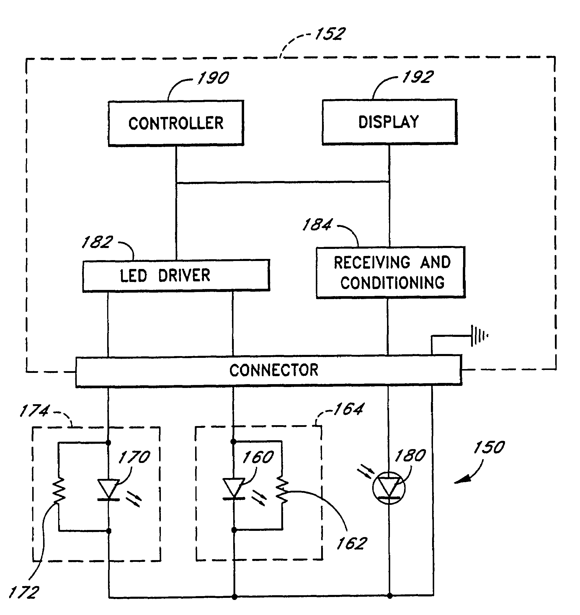
[0043]The present invention has applicability to the use of medical probes and LEDs in general. However, an understanding is facilitated with the following description of the application of the principles of the present invention to oximetry.

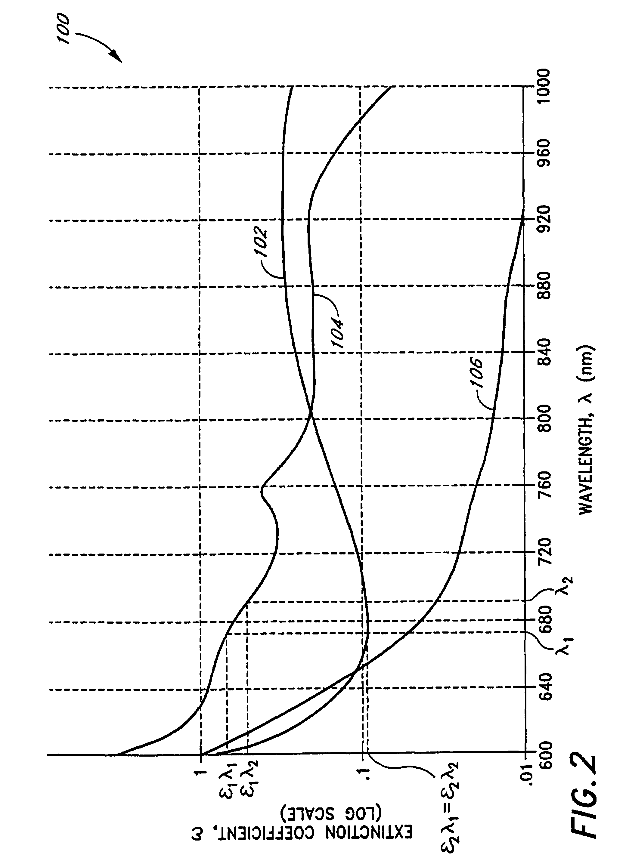
[0044]The advantages of noninvasive techniques in monitoring the arterial oxygen (or other constituents) saturation of a patient are well-known. In oximetry, light of a known wavelength is transmitted through a medium (e.g., a human digit such as a finger) under test. The light energy is partially absorbed and scattered by the constituents that make up the medium as the light propagates through the medium. The absorption and scattering of the light energy by any given constituent depends upon the wavelength of the light passing through the constituent, as well as several other parameters. The absorption by a constituent is characterized with what is known as the extinction coefficient.

[0045]FIG. 2 represents an exemplary graph 100 of the relatio...


PUM

PropertyMeasurementUnit
voltage amplitudeaaaaaaaaaa
operating frequencyaaaaaaaaaa
voltage amplitudeaaaaaaaaaa

Abstract

Embodiments of the present disclosure include an oximeter sensor system including a reusable portion including a substantially rigid connector connected to an end of a cable. The substantially rigid connector includes an electronic element housing at least one electronic component of a probe. The system also includes a disposable portion including a flexible wrap comprising a substantially rigid connection port shaped to receive the substantially rigid connector in a releasably securable manner.

Description

[0001]This application is a continuation of application Ser. No. 10 / 005,711, filed Nov. 8, 2001, now U.S. Pat. No. 6,678,543, which is a continuation of application Ser. No. 09 / 451,151, filed Nov. 30, 1999, now U.S. Pat. No. 6,397,091, which is a continuation of application Ser. No. 09 / 016,924, filed on Feb. 2,1998, now U.S. Pat. No. 6,011,986, which is a continuation of application Ser. No. 08 / 478,493, filed on Jun. 7,1995, now U.S. Pat. No. 5,758,644. The present application incorporates each of the foregoing disclosures herein by reference.BACKGROUND OF THE INVENTION[0002]1. Field of the Invention[0003]The present invention relates generally to more effective calibration and use of light-emitting diodes. More particularly, the present invention relates to an apparatus and method of calibrating and using light-emitting diodes in a sensor for use with an oximeter system.[0004]2. Description of the Related Art[0005]Light-emitting diodes (LEDs) are used in many applications. In certa...

Claims


Application Information

Patent Timeline
Patent Type & Authority Patents(United States)
IPC IPC(8): A61B5/145H05B44/00A61B5/00A61B5/1455A61B5/1495G01J3/10G01J3/28G01N21/01G01N21/25G01N21/27G01N21/39G01N21/64G05F3/08H05B37/02
CPCA61B5/14552A61B5/1495A61B5/6826A61B5/6838G01J3/02G01J3/0254G01J3/027G01J3/0275G01J3/0291G01J3/10G01N21/255G01N21/274G01N21/31G01N21/3151G01N21/39A61B5/0205A61B2562/08G01J2003/2866G01N2021/3144G01N2201/0627A61B5/02427
Inventor DIAB, MOHAMED KHEIRKIANI, MASSI E.RAGSDALE, CHARLES ROBERTLEPPER, JR., JAMES M.
Owner JPMORGAN CHASE BANK NA
Why Eureka
Try Eureka