Lithographic apparatus, device manufacturing method and variable attenuator

a technology of variable attenuator and lithographic apparatus, which is applied in the direction of cement mixing apparatus, printing equipment, instruments, etc., can solve the problems of adversely affecting the operation of the rest, adversely affecting the throughput and yield of wafers, and insufficient to maintain the required high dose accuracy at the wafer and high wafer throughpu

Inactive Publication Date: 2006-12-05
ASML NETHERLANDS BV
View PDF11 Cites 8 Cited by
  • Summary
  • Abstract
  • Description
  • Claims
  • Application Information

AI Technical Summary

Benefits of technology

[0007]The use of such a variable attenuator allows the radiation dose at the wafer to be accurately controlled substantially without adversely affecting other performance parameters, such as the uniformity and or telecentricity of the apparatus, while maintaining a high throughput of wafers. More particularly the attenuator allows the intensity of the projection beam to be varied continuously without changing the position of the beam, whether the input beam is converging, diverging or parallel. Furthermore the attenuator can be controlled in dependence on the output from a dose monitoring sensor positioned to monitor the dose received by the wafer. Additionally the back sides of the mirrors can be cooled in a straightforward manner to offset the heat absorption at high attenuation rates. This may allow most of the heat load to be absorbed in relatively simple, and therefore low cost, optics, thus making the design of the apparatus less complicated and therefore more cost efficient.
[0011]Furthermore the reflective surfaces may be positioned relative to the input beam such that the radiation is focussed at a point between the reflective surfaces. This is advantageous as it allows the reflective surfaces to be decreased in size as compared with the case in which the focus is not between the two reflective surfaces, particularly when small grazing angles of incidence are used or when the beam has a large cross-section. Alternatively the reflective surfaces may be positioned relative to the input beam such that the radiation is focussed at a point beyond the second reflective surface or at a point before the first reflective surface.

Problems solved by technology

However known attenuators used in such an application tend to adversely affect the operation of the rest of the illumination system, for example by changing the position of the illumination beam, and / or are difficult to control in such a manner as to accurately adjust the dose at the wafer and to control the speed of adjustment of the dose might be an issue, thereby adversely affecting the throughput and yield of wafers.
However the use of only three different attenuation levels, and a fourth level in which no attenuation is provided corresponding to the blade being moved out of the radiation path, may be insufficient to maintain the required high dose accuracy at the wafer and high wafer throughput based on variation of this dose.
Apart from the fact that such attenuators do not provide continuously variable levels of attenuation, they have the disadvantage that cooling may be complicated because of the complexity of the attenuator blades or poor cooling capabilities of gas cells.
Furthermore the use of a blade in the beam may adversely affect certain factors determining the performance of the system, such as the uniformity of the projection beam.

Method used


Image

  • Lithographic apparatus, device manufacturing method and variable attenuator
  • Lithographic apparatus, device manufacturing method and variable attenuator
  • Lithographic apparatus, device manufacturing method and variable attenuator

Examples


Embodiment Construction

[0033]While the following description refers to specific embodiments of the invention, it will be appreciated that the invention may be practiced otherwise than as described below. The description is not intended to limit the invention.

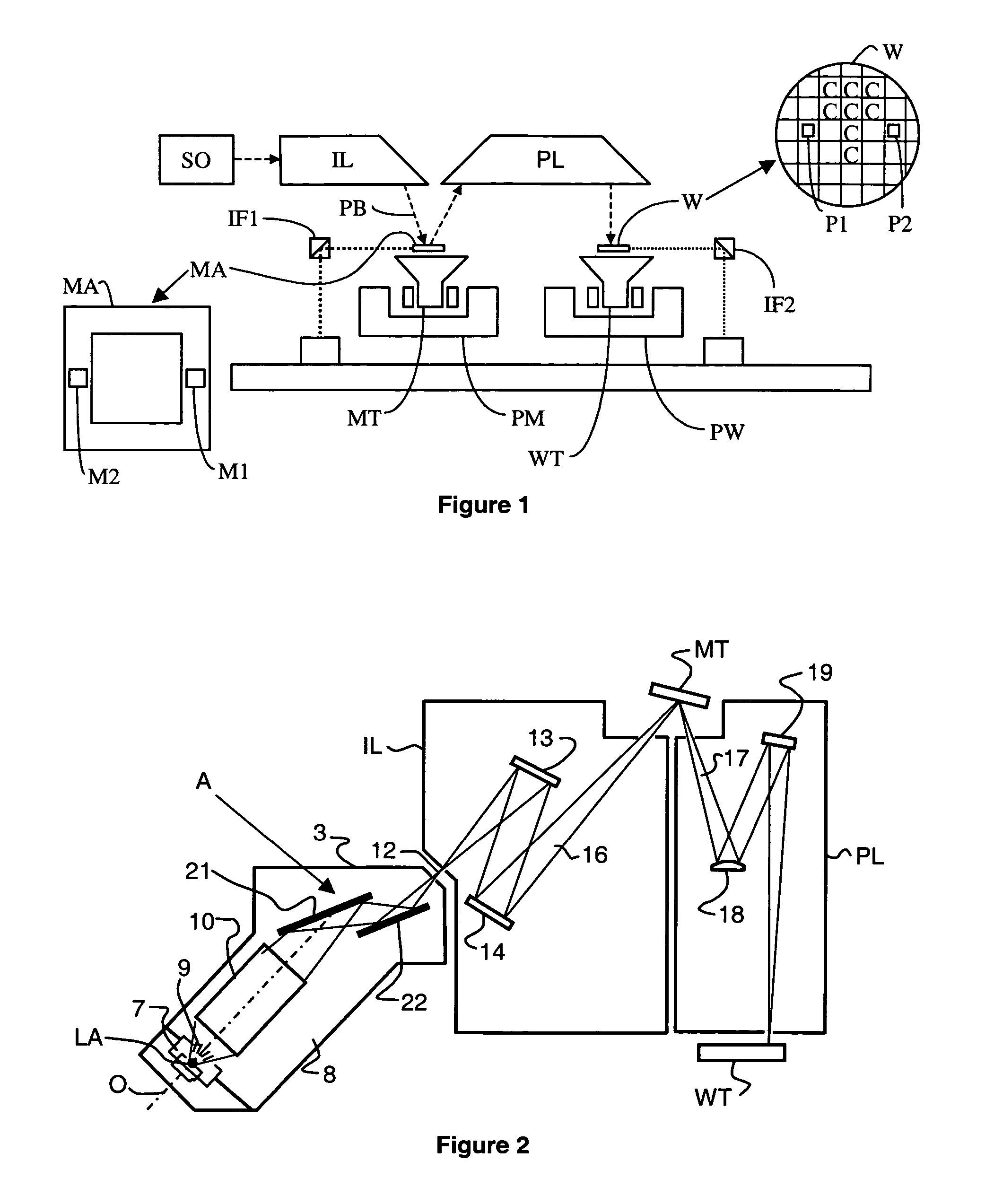
[0034]FIG. 1 schematically depicts a typical lithographic apparatus. The apparatus comprises:

[0035]an illumination system IL for providing a projection beam PB of radiation (e.g. UV or EUV radiation).

[0036]a first support structure (e.g. a mask table) MT for supporting patterning structure (e.g. a mask) MA and connected to first positioning means PM for accurately positioning the patterning structure with respect to item PL;

[0037]a substrate table (e.g. a wafer table) WT for holding a substrate (e.g. a resist-coated wafer) W and connected to second positioning means PW for accurately positioning the substrate with respect to item PL; and

[0038]a projection system (e.g. a reflective projection lens) PL for imaging a pattern imparted to the projection be...


PUM

PropertyMeasurementUnit
anglesaaaaaaaaaa
anglesaaaaaaaaaa
angles of grazing incidenceaaaaaaaaaa

Abstract

A lithographic apparatus includes an illumination system for providing a projection beam of radiation, a support structure for supporting patterning structure for imparting a pattern to the projection beam, a substrate table for holding a wafer and a projection system for projecting the patterned beam onto a target portion of the wafer. In order to permit control of the radiation dose at the wafer so that the throughput of wafers can be optimised, a variable attenuator is provided to vary the intensity of the projection beam while not changing the position of the beam. The variable attenuator includes two parallel mirrors positioned such that an input beam of radiation is incident on a first of the mirrors by which it is reflected towards a second of the mirrors by which the beam is reflected to produce an output beam of radiation of required intensity for input to the illumination system, and a tilting mechanism for tilting the mirrors such that the mirrors remain parallel to one another and the angles of incidence of the beams on the mirrors are changed so as to vary the intensity of the output beam. This allows the intensity of the projection beam to be varied continuously without changing the position of the beam, whether the input beam is converging, diverging or parallel.

Description

FIELD OF THE INVENTION[0001]The present invention relates generally to a lithographic apparatus, a device manufacturing method and more particularly to a lithographic apparatus having a variable attenuator.BACKGROUND TO THE INVENTION[0002]A lithographic apparatus is a machine that applies a desired pattern onto a target portion of a substrate. Lithographic apparatus can be used, for example, in the manufacture of integrated circuits (ICs). In that circumstance, a patterning structure, which is alternatively referred to as a mask or a reticle, may be used to generate a circuit pattern corresponding to an individual layer of the IC, and this pattern can be imaged onto a target portion (e.g. comprising part of, one or several dies) on a substrate (e.g. a silicon wafer) that has a layer of radiation-sensitive material (resist). In general, a single substrate will contain a network of adjacent target portions that are successively exposed. Known lithographic apparatus include so-called s...

Claims


Application Information

Patent Timeline
Patent Type & Authority Patents(United States)
IPC IPC(8): G03B27/72G03B27/42G03B27/54H01L21/027G03F7/20
CPCG03F7/70558G03F7/20
Inventor VOORMA, HARM-JANVAN DIJSSELDONK, ANTONIUS JOHANNES JOSEPHUSMICKAN, UWE
Owner ASML NETHERLANDS BV
Why Eureka
Try Eureka