Bone growth via periosteal distraction

Inactive Publication Date: 2005-07-21
ODRICH RONALD B
View PDF4 Cites 31 Cited by
  • Summary
  • Abstract
  • Description
  • Claims
  • Application Information

AI Technical Summary

Problems solved by technology

This poses a particular problem in cases where implants are being considered for replacing

Method used


Image

  • Bone growth via periosteal distraction
  • Bone growth via periosteal distraction
  • Bone growth via periosteal distraction

Examples


Embodiment Construction

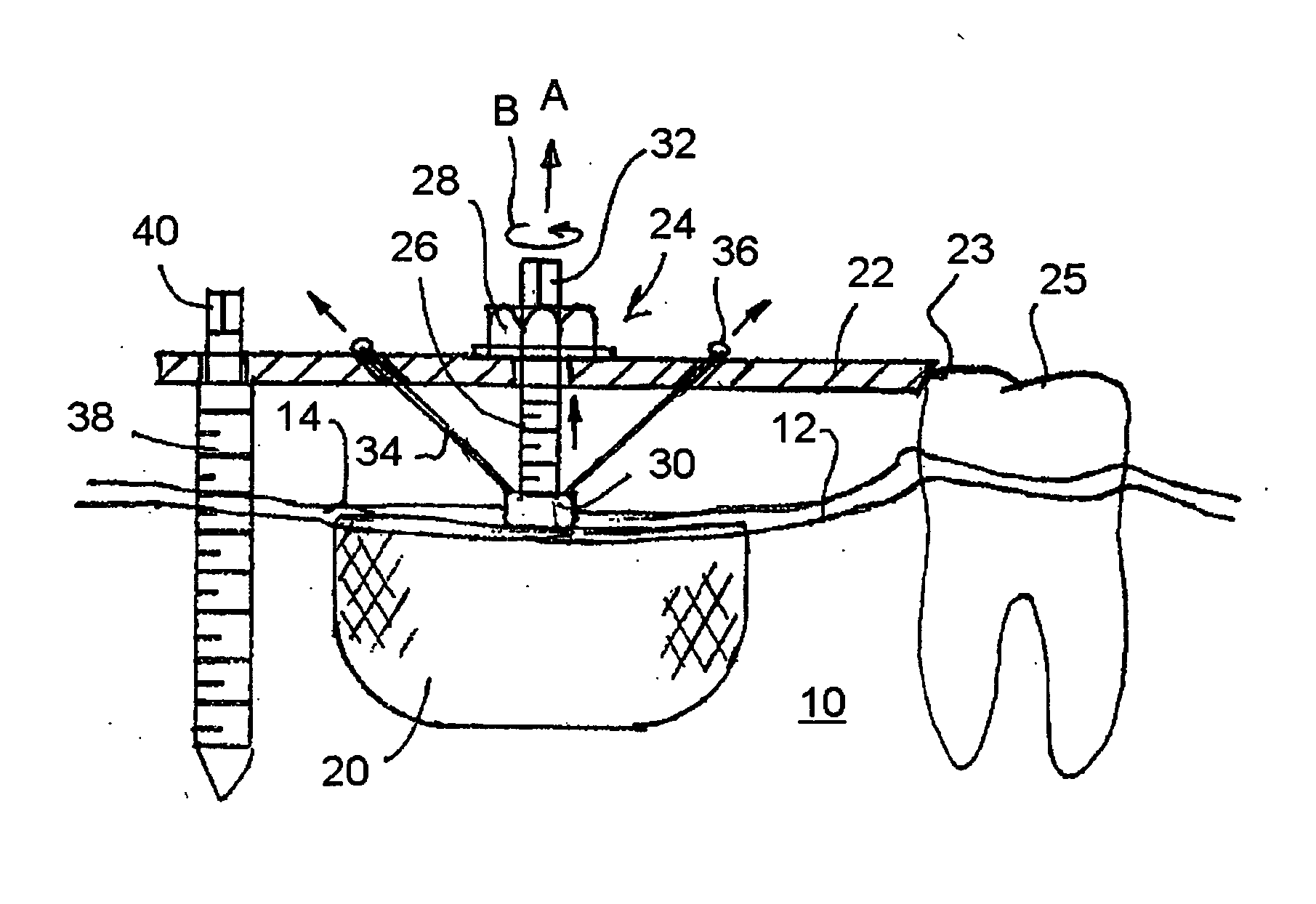
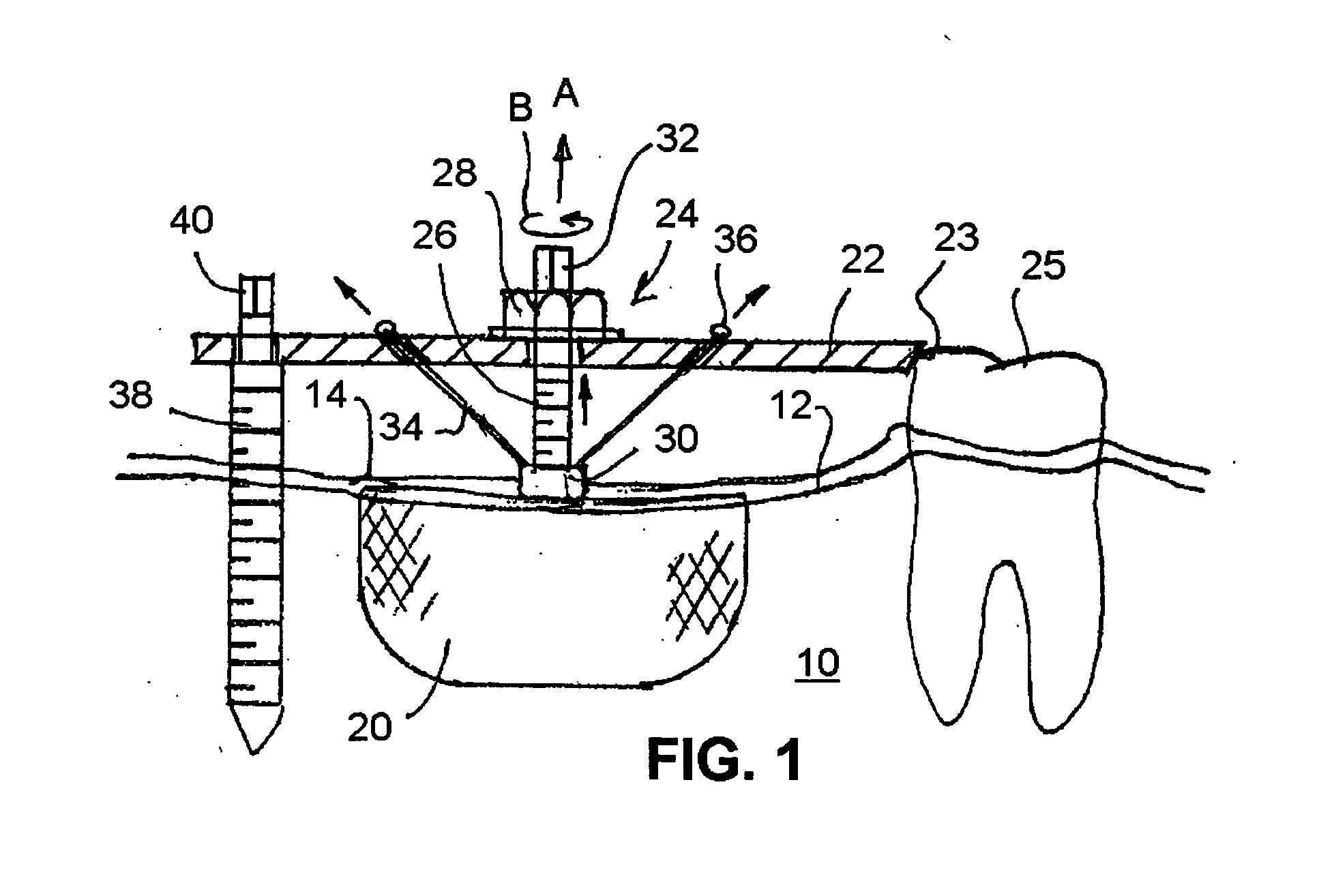
[0018] Referring now to the drawings in which like reference numerals are used to refer to the same or functionally similar elements, FIG. 1 illustrates a jawbone 10 with one tooth 25 and having an edentulous or toothless area 12 extending at least to a pin 38. Gingival tissue or gum 14 covers the jawbone and edentulous area and surrounds the tooth in usual fashion. As is know, the jawbone in area 12 tends to shrink or recede after the teeth have been lost. If a dental implant is desired in area 12 to replace the missing teeth, however, a certain minimum amount of bone must be present.

[0019] According to the present invention, bone can be induced to grown occlusally, that is outwardly or normally from the crestal surface of the jawbone.

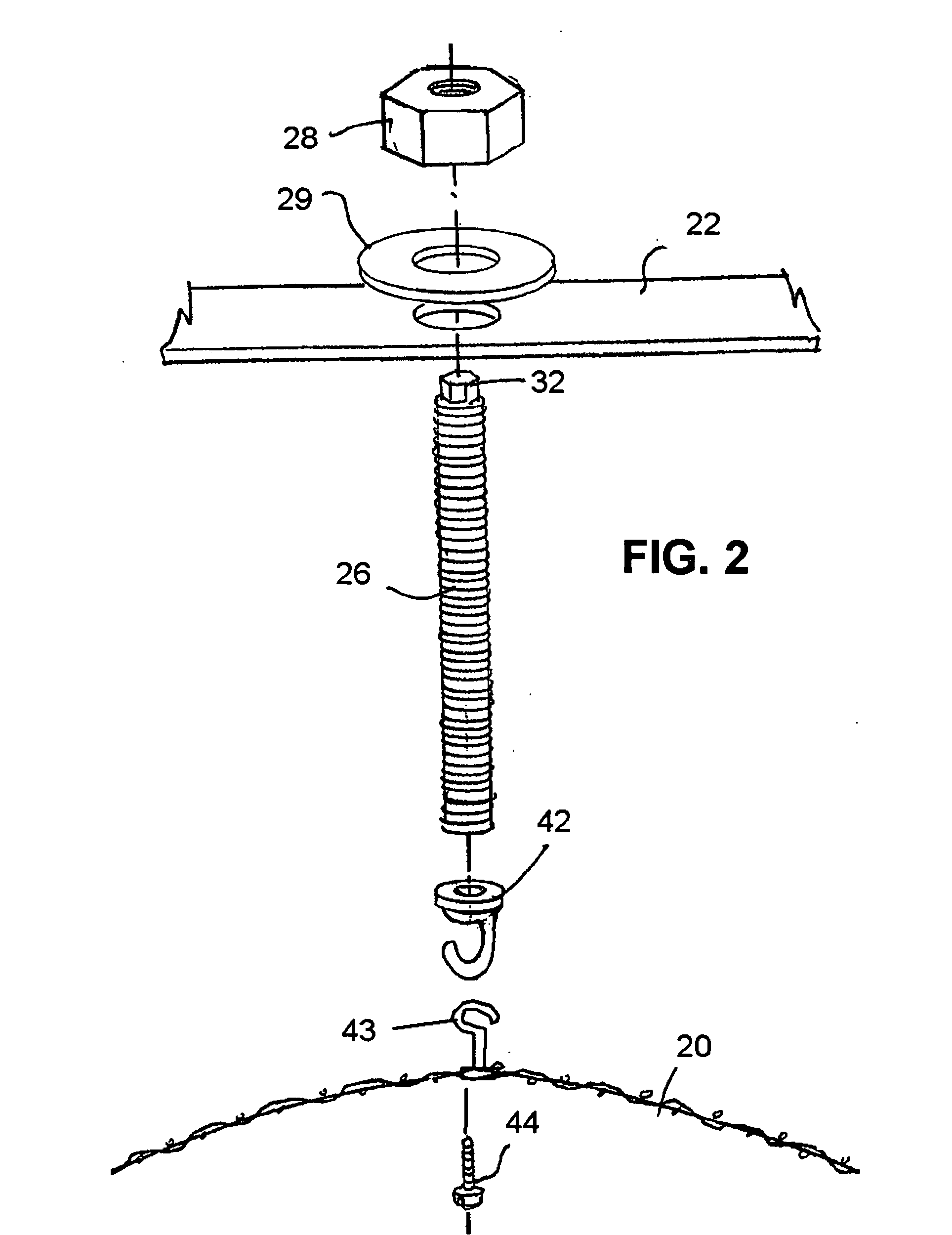
[0020] The periosteal distraction osteogenesis method and apparatus of the invention comprises applying to the surface of the living bone 10 that is covered by soft tissue 14 and at which bone growth is desired, a sheet member 20 for covering at lea...


PUM


Abstract

A periosteal distraction osteogenesis method and apparatus uses a sheet member for covering a surface of living bone that is, in turn, covered by soft periosteal tissue. The sheet member is under the soft tissue and over an area where bone growth outwardly and normally from the bone surface is desired. The method and apparatus requires distracting the sheet member away from the portion of the bone surface at which bone growth is desired, for causing growth of the bone outwardly and normally from the bone surface.

Description

CROSS REFERENCE TO RELATED APPLICATION [0001] This is a continuation-in-part of application Ser. No. 10 / 761,840 filed Jan. 21, 2004, which is incorporated here by reference.FIELD AND BACKGROUND OF THE INVENTION [0002] The present invention relates generally to the field of osteogenesis (bone growth), and in particular to a new and useful method and apparatus for growing bone in selected areas of a human or animal subject, particularly, but not exclusively, for growing bone at the crest of the jawbone. [0003] It is often desirable to encourage bone to grow. Any bone fracture to be treated, for example, relies on bone growth to knit the bone back together in the fractured area. [0004] The field of distraction osteogenesis is known for causing facial and other bones to grow as exemplified in U.S. Pat. Nos. 5,769,850; 5,810,812; and 5,976,142 to Martin Chin. Also see the article in Vol. 12, No. 2, Spring 200, Orthodontic Dialogue, “Distraction Osteogenesis: A New Frontier in Correcting ...

Claims


Application Information

Patent Timeline
IPC IPC(8): A61B17/56A61B17/66A61F2/30A61F5/00A61F5/04
CPCA61B17/66A61C8/0006A61B17/666A61B17/663A61F2/2846A61F2002/30471A61F2002/30507A61F2002/30563
Inventor ODRICH, RONALD B.
Owner ODRICH RONALD B
Why Eureka
Try Eureka