Electromotion toothbrush rotatable in positive or reverse direction

Inactive Publication Date: 2005-07-28
JUNG CHOONG HYUN
View PDF4 Cites 6 Cited by
  • Summary
  • Abstract
  • Description
  • Claims
  • Application Information

AI Technical Summary

Benefits of technology

[0013] The present invention is designed to solve the problems described above. Therefore, it is an object of the present invention to provide an electromotion toothbrush which can easily convert the rotational direction of a driving motor into a positive or reverse direction by the manipulation of direction conversion switching circuitry. It is another object of the invention to provide an electromotion toothbrush which implements easy removal of foreign substances between teeth and which a user can conveniently carry.
[0014] In order to achieve the objects described above, an electromotion toothbrush according to the present invention comprises: a grip which can accommodate a driving motor for generating rotational force, a power supply for supplying power to the driving motor and a decelerator connected to the driving motor for decelerating the rotational speed of the output shaft of the driving motor; a direction conversion switch provided between the power supply and the driving motor for easily converting the rotational direction of the driving motor into a positive or reverse direction by the manipulation of the direction conversion switching circuitry;, a rotating toothbrush bar consisting of a rotating rod installed to the decelerator and a removable bristle part which is positioned on the rotating rod and on which toothbrush bristles are planted; and a removable protective stand installed at one side of the top of the grip parallel to the rotating toothbrush bar.
[0016] The electromotion toothbrush further comprises a toothbrush cover having at least one hole on its top side and a holder for easy transport at one external side.

Problems solved by technology

The methods described above, such as the Bass method, the up-and-down or circular motion method, etc., however, have a disadvantage that makes it difficult to properly brush teeth by means of a manual toothbrush.
It is more difficult for a user who is accustomed to improper toothbrushing habits to obtain such a proper toothbrushing method.
Moreover, the up-and-down and circular motions are very annoying even to an actually skillful user, so that, in most cases, toothbrushing is carried out only in a to-and-fro motion.
Consequently, since foreign substances cannot efficiently be removed, manual toothbrushing by the methods described above may injure a user's mouth, for example, causing inflammation on user's gums, due to wrong toothbrushing habits.
Conventional electromotion toothbrushes have been invented for a simple motion or circular motion, wherein the electromotion toothbrush by a simple motion needs a small amount of user's physical force when toothbrushing but can not achieve efficient removal of foreign substances by means of a simple to-and-fro motion.
Most of the rotating electromotion toothbrushes rotate only in one direction, making this toothbrush inconvenient to use since a user has to alternate his / her hands to hold the toothbrush for brushing the upper and lower teeth in opposite directions.
Most conventional electromotion toothbrushes are also configured by an integrated type which does not allow replacement of toothbrush bristles, and are disadvantageous in that it can not properly protect parts in a user's mouth other than teeth, gaps between teeth, etc. through rotation of the toothbrush bristles.
A rotating electromotion toothbrush also has a disadvantage in that it cannot satisfactorily remove foreign substances between teeth.
An interdental toothbrush as shown in FIG. 5, however, requires a separate toothbrush for cleaning teeth because it can only clean gaps between teeth.

Method used


Image

  • Electromotion toothbrush rotatable in positive or reverse direction
  • Electromotion toothbrush rotatable in positive or reverse direction
  • Electromotion toothbrush rotatable in positive or reverse direction

Examples


Embodiment Construction

[0023] Hereinafter, preferred embodiments of the present invention will be described in detail with reference to the accompanying drawings.

[0024] The following embodiment, however, is intended to illustrate the present invention, not to limit the scope of the invention. Simple changes and modifications in design of the invention can be easily implemented by those skilled in the art, and such changes and modifications are considered to be covered in the scope of the invention.

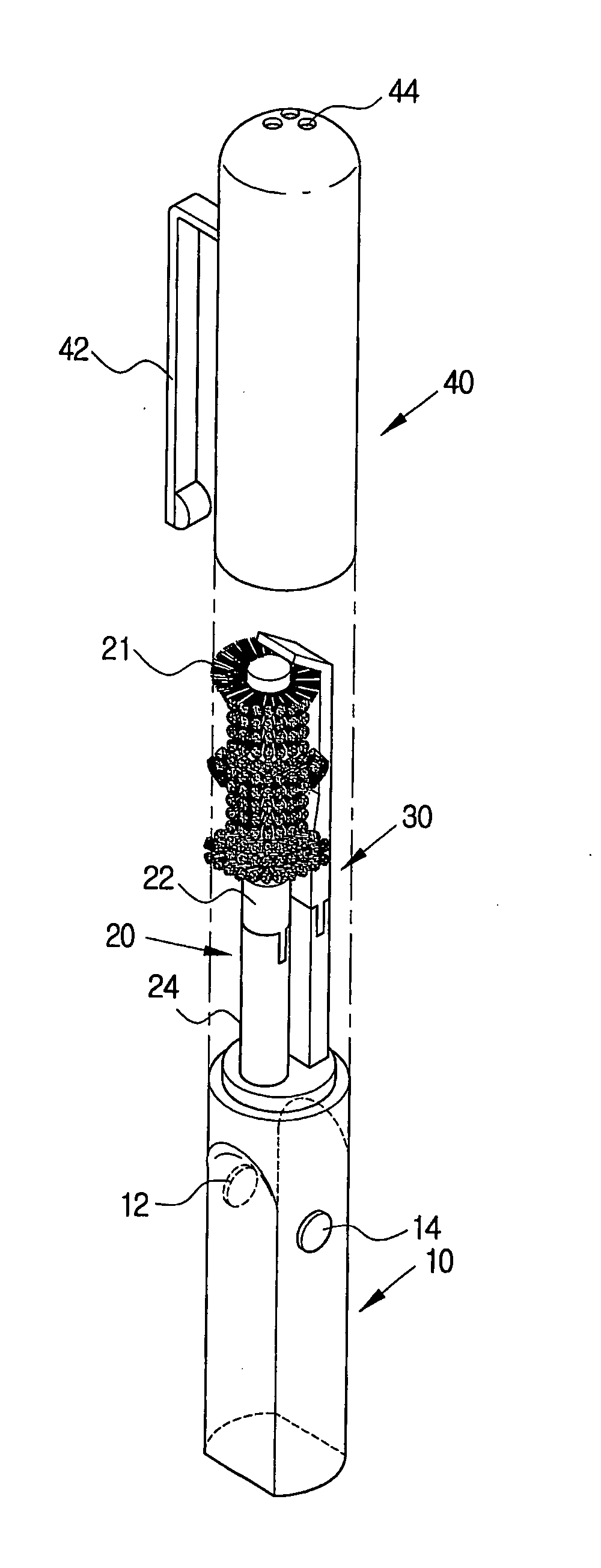
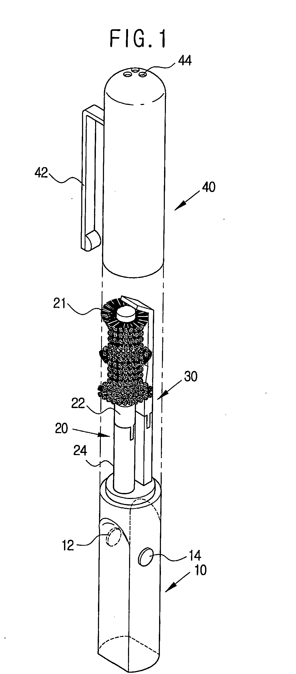
[0025]FIG. 1 shows a perspective view of an electromotion toothbrush according to one embodiment of the invention.

[0026] As shown in FIG. 1, the electromotion toothbrush according to the invention comprises a grip 10, direction conversion buttons 12 and 14, a rotating toothbrush bar 20, a protective stand 30 and a toothbrush cover 40.

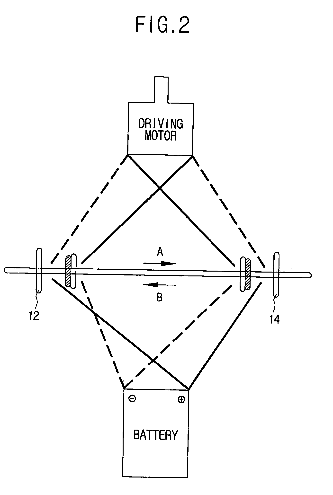
[0027] The grip 10 is provided with a driving motor, a power supply and a decelerator (not shown) therein.

[0028] The power supply, which may be a dry cell or a storage battery,...


PUM


Abstract

The present invention relates to an electromotion toothbrush, and more particularly to an electromotion toothbrush which easily converts rotational direction thereof by simple manipulation of a switching circuit and easily removes foreign substances in gaps between teeth. For the purpose, the present invention comprises: a grip which can accommodate a driving motor for generating rotational force, a power supply for supplying power to the driving motor and a decelerator connected to the driving motor for decelerating the rotational speed of the output shaft of the driving motor; a direction conversion switch provided between the power supply and the driving motor for easily converting the rotational direction of the driving motor into a positive or reverse direction; a rotating toothbrush bar consisting of a rotating rod installed to the decelerator and a removable bristle part which is positioned on the rotating rod and on which toothbrush bristles are planted; and a removable protective stand installed at one side of the top of the grip parallel to the rotating toothbrush bar. The bristle part has longer bristles on the upper part, the middle and the lower part thereof, than that provided to the other parts.

Description

TECHNICAL FIELD [0001] The present invention relates to an electromotion toothbrush, and more particularly to an electromotion toothbrush of which rotational direction is easily converted by the manipulation of direction conversion switching circuitry, which easily removes foreign substances between teeth and is convenient to carry. BACKGROUND ART [0002] A toothbrush is a mouth-washing tool used to protect teeth, gaps between teeth, etc. from germs harmful to the human body, and is classified as either a manual toothbrush or an electromotion toothbrush, wherein a user holds the grip of the manual toothbrush and rotates the toothbrush in a given direction for operation thereof, and the electromotion toothbrush is rotated by an electromotor such as a driving motor. [0003] Several types of toothbrushing can be performed using a conventional toothbrush. [0004] Some of the uses of the manual toothbrush involve the “scraping method” in which a user brings the manual toothbrush into contac...

Claims


Application Information

Patent Timeline
IPC IPC(8): A46B13/02A46B9/04A46B13/00A46B17/08A61C17/00A61C17/22A61C17/26
CPCA46B9/04A61C17/26A46B2200/108A46B13/001A46B13/02
Inventor JUNG, CHOONG-HYUN
Owner JUNG CHOONG HYUN
Why Eureka
Try Eureka