Gear shift assembly
- Summary
- Abstract
- Description
- Claims
- Application Information
AI Technical Summary
Benefits of technology
Problems solved by technology
Method used
Image


Examples
Embodiment Construction
.
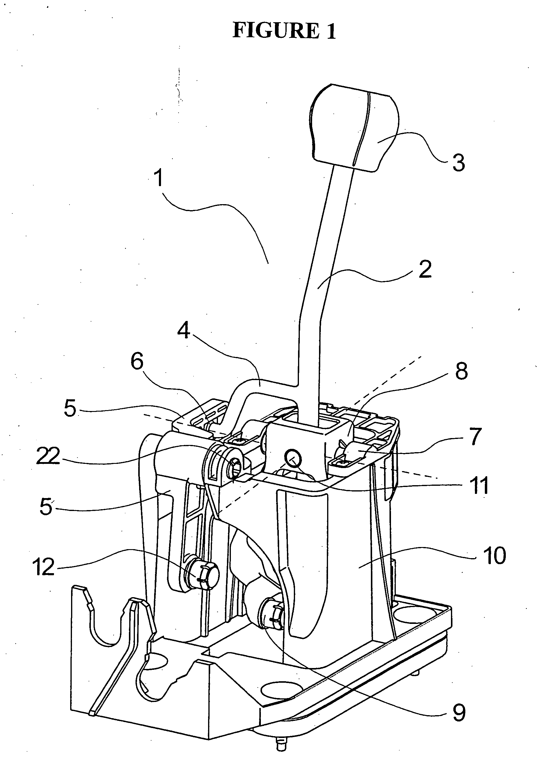
[0022]FIG. 1 shows a gear shift assembly 1 for automobiles with a gear shift lever 2. A gear shift knob 3 is screwed or pushed on the upper free end of the gear shift lever 2. A gear shift finger 4 is formed on the gear shift lever 2, which has an angled shape and is supported in a gear selection lever 5 by a ball joint 6. The gear shift lever 2 is also connected with a crosspiece 8 by a bolt connection 7. The bolt connection 7 makes it possible to pivot the gear shift lever 2 in the direction of a gear selection motion, with the depicted embodiment enabling shifting between the various gear shift gates by pivoting the gear shift lever 2 in the direction of the gear selection motion transversely to the travel direction of the automobile. For example, for automatic transmissions, two different gear shift gates can be arranged in the gear shift assembly 1, but the gear shift assembly 1 may also have three or more gear switch gates, for example in manual H-gear boxes with up to six fo...
PUM
 Abstract
Description
Claims
Application Information