Materials and methods for imprint lithography

a technology of imprint lithography and materials, applied in the field of imprint lithography, can solve the problems of reducing throughput, reducing the efficiency of imprinting, and limiting the operation life of prior release layers, so as to reduce, if not prevent, the formation of voids during imprinting, and efficiently wet the imprint material.

Inactive Publication Date: 2005-07-28
MOLECULAR IMPRINTS
View PDF99 Cites 74 Cited by
  • Summary
  • Abstract
  • Description
  • Claims
  • Application Information

AI Technical Summary

Problems solved by technology

A priori release layers, however, typically have a limited operational life.
This can result in several hours of down-time for a given imprint template, thereby reducing throughput.
Additionally, the molecular structure of the a priori release layer may limit the minimization of the minimum feature dimension that is printed.
The BARC layer was used to prevent intermixing between the imprinting material and the transfer layer, which intermixing may be particularly problematic when using an imprinting material comprised of low viscosity acrylate components because such components have solvency toward many polymers.
Such intermixing may cause problems, such as, for example, and without limitation, distortion of features when the imprint template is separated from the substrate after exposure to polymerizing radiation.
In particular, this can be problematic when feature thicknesses are as small as 50 nm to 100 nm.
Despite the above-described successful imprinting, material voids were observed when we imprinted a high feature density imprint template using the above-described imprinting method.

Method used


Image

  • Materials and methods for imprint lithography
  • Materials and methods for imprint lithography
  • Materials and methods for imprint lithography

Examples


Embodiment Construction

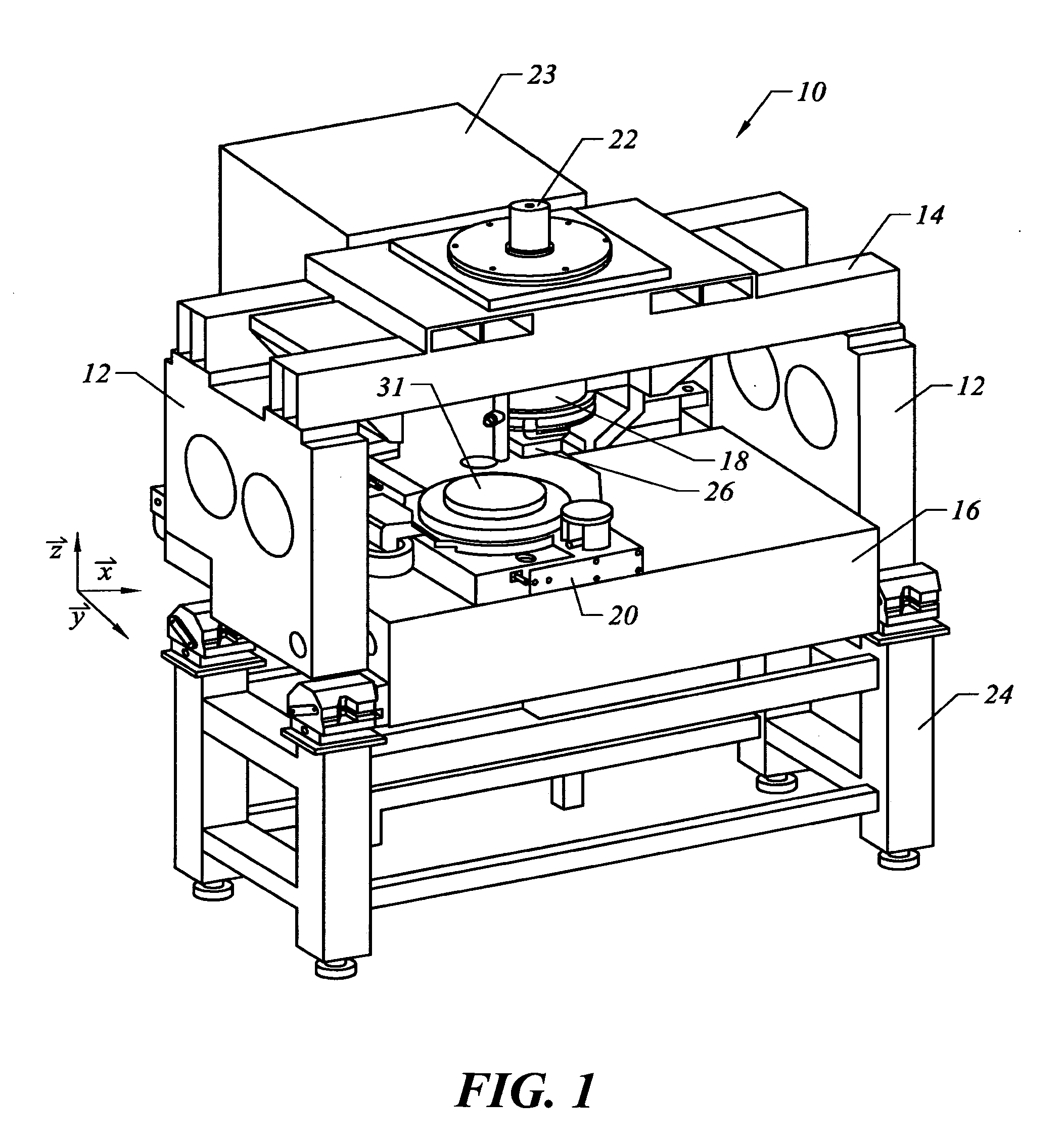
[0017]FIG. 1 shows lithographic system 10 that may be used to carry out imprint lithography in accordance with one or more embodiments of the present invention and utilizing imprinting materials fabricated in accordance with one or more embodiments of the present invention. As shown in FIG. 1, system 10 includes a pair of spaced-apart bridge supports 12 having bridge 14 and stage support 16 extending therebetween. As further shown in FIG. 1, bridge 14 and stage support 16 are spaced-apart. Imprint head 18 is coupled to bridge 14, and extends from bridge 14 toward stage support 16. Motion stage 20 is disposed upon stage support 16 to face imprint head, and motion stage 20 is configured to move with respect to stage support 16 along X- and Y-axes. Radiation source 22 is coupled to system 10 to impinge actinic radiation upon motion stage 20. As further shown in FIG. 1, radiation source 22 is coupled to bridge 14, and includes power generator 23 connected to radiation source 22.

[0018] ...


PUM

PropertyMeasurementUnit
thicknessaaaaaaaaaa
thicknessaaaaaaaaaa
thicknessesaaaaaaaaaa

Abstract

One embodiment of the present invention relates to an imprinting material for imprint lithography that includes the surfactant 3M™ Novec™ Fluorosurfactant FC-4432, and another embodiment of the present invention relates to a method for imprint lithography that uses the imprinting material.

Description

TECHNICAL FIELD OF THE INVENTION [0001] One or more embodiments of the present invention relate generally to imprint lithography. In particular, one or more embodiments of the present invention relate to materials and methods for imprint lithography. BACKGROUND OF THE INVENTION [0002] Micro-fabrication involves the fabrication of very small structures, for example, and without limitation, structures having features on the order of micro-meters or smaller. One area in which micro-fabrication has had a sizeable impact is in processing of integrated circuits. As the semiconductor processing industry continues to strive for larger production yields while increasing the circuits per unit area formed on a substrate, micro-fabrication becomes increasingly important since micro-fabrication provides greater process control while allowing a reduction in the minimum feature dimension of the structures formed. Other areas of development in which micro-fabrication have been employed include biot...

Claims


Application Information

Patent Timeline
Patent Type & Authority Applications(United States)
IPC IPC(8): B41C1/10B41M7/00B41N1/00G03F7/00
CPCB41C1/10B41M7/0072B82Y10/00B41M7/0081B82Y40/00G03F7/0002Y10S977/887B82Y30/00
Inventor XU, FRANK Y.LAD, PANKAJ B.MCMACKIN, IAN M.
Owner MOLECULAR IMPRINTS
Why Eureka
Try Eureka