Display device and a method of controlling the same

a technology of a display device and a control method, which is applied in the field of display devices, can solve the problems and achieve the effect of extremely deteriorating workability of spreadsheet jobs or document compositions on the pc screen

Inactive Publication Date: 2005-07-28
HITACHI LTD
View PDF5 Cites 31 Cited by
  • Summary
  • Abstract
  • Description
  • Claims
  • Application Information

AI Technical Summary

Benefits of technology

[0010] In order to solve this problem, a object of the invention is to provide a display device for displaying a PC video signal and a TV video signal at the same time, comprising a frame memory for storing display information corresponding to resolution of the display device, a scaling unit for changing the resolution of the TV video signal, and a video signal synthesis unit for recording the PC video signal, the PC display information corresponding to the scaled TV video signal and the TV video signal in an area free of superposition in the frame memory, wherein the PC video signal and the TV video signal are displayed in tiles.

Problems solved by technology

In the conventional method of using the TV receiver as a PC monitor at the same time, the user conducting the spreadsheet job or the document composition work on the PC screen by mouse or keyboard operation of the PC encounters the serious problem that part of the PC monitor screen (large picture) is hidden behind the TV screen (large picture) and the workability of the spreadsheet job or the document composition on the PC screen is extremely deteriorated.

Method used


Image

  • Display device and a method of controlling the same
  • Display device and a method of controlling the same
  • Display device and a method of controlling the same

Examples


first embodiment

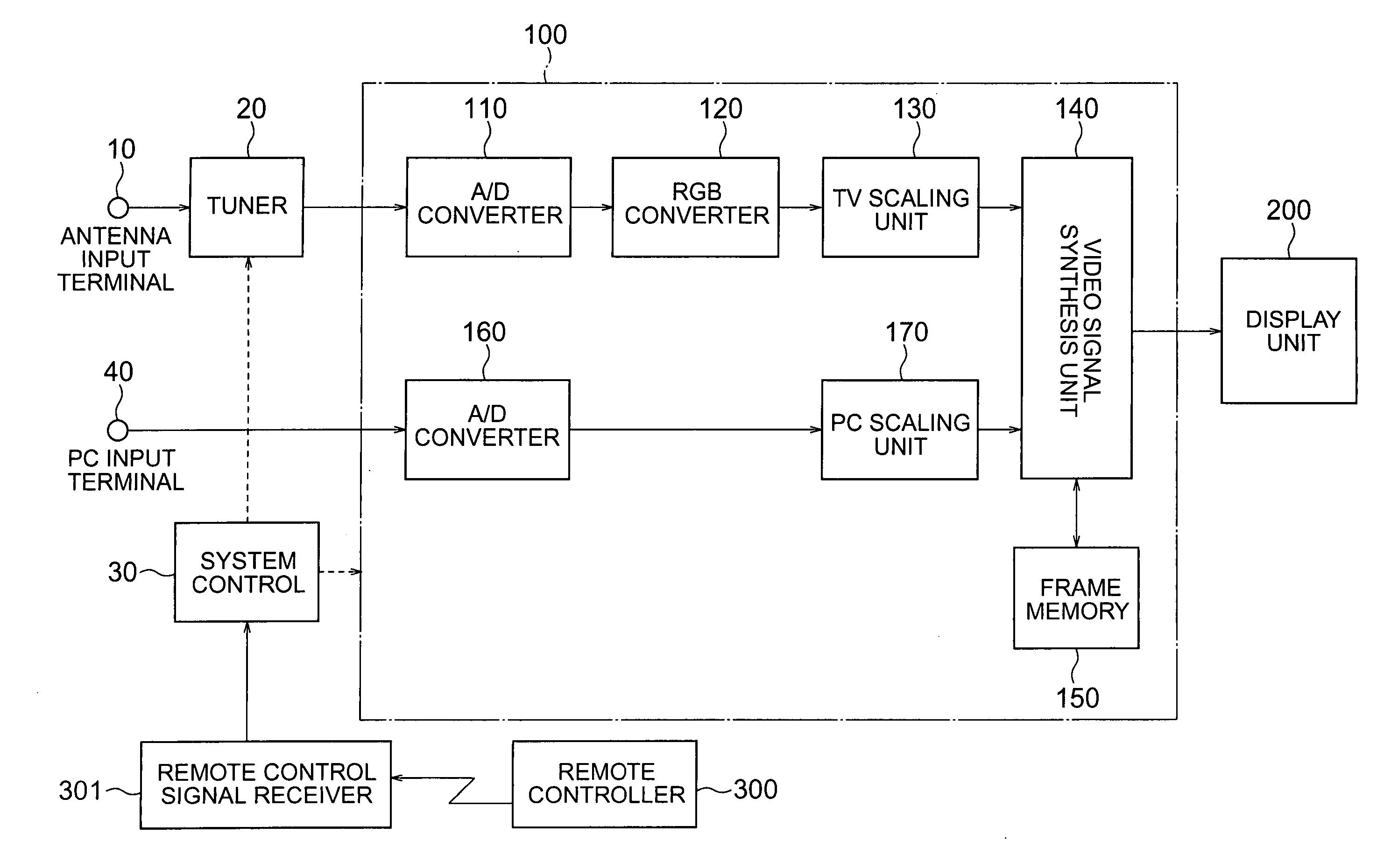
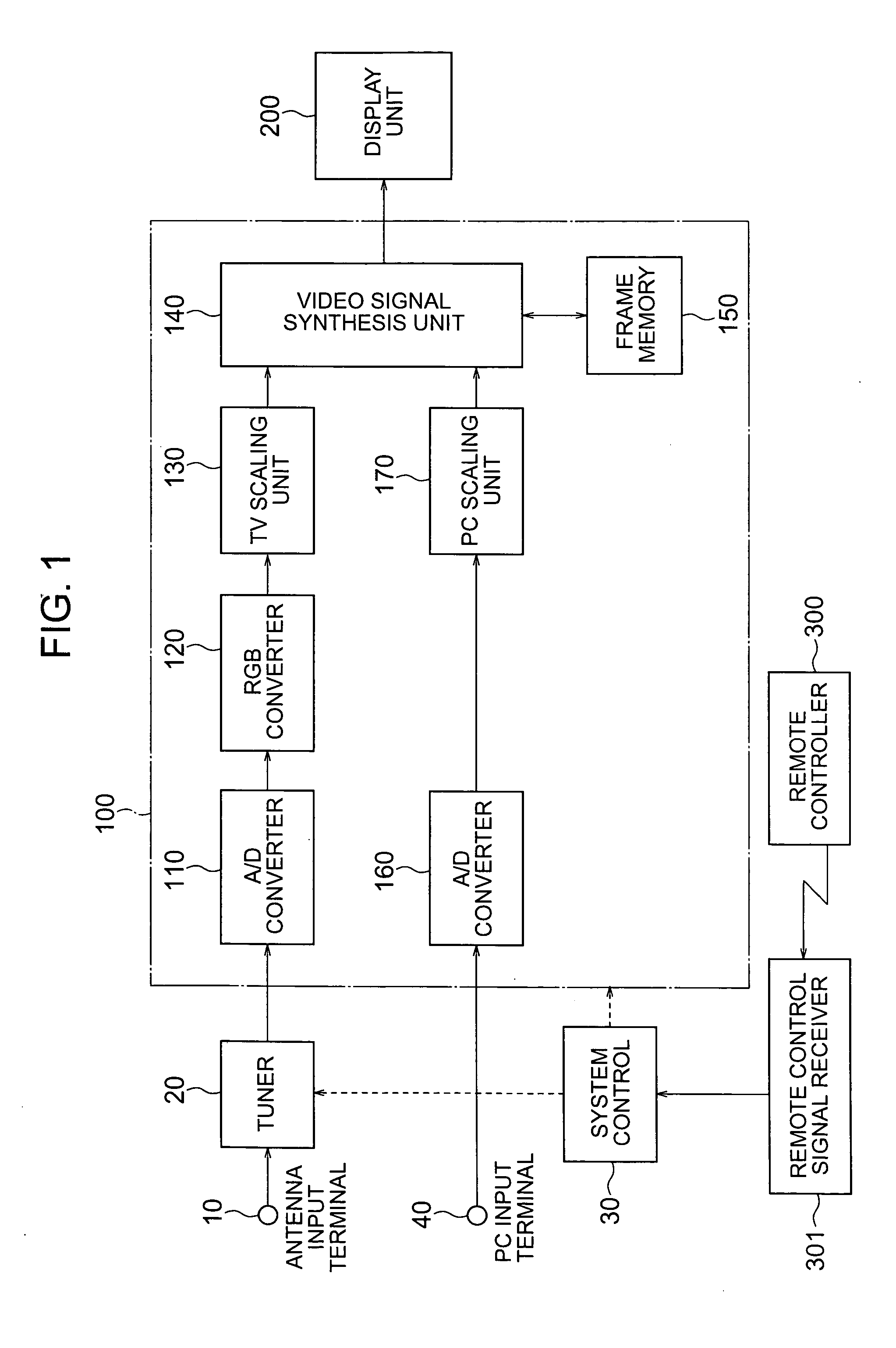
[0032]FIG. 1 is a block diagram showing a display device according to the invention. The display device according to the embodiment shown in FIG. 1 has the function of receiving a TV broadcast signal and displaying a TV video signal, the function of displaying a PC video signal output from the PC and the function of displaying the PC video signal and the TV video signal at the same time without mutual superposition.

[0033] The type and the resolution of the video signal display device shown in FIG. 1 are not specifically limited and any display device such as a CRT, the liquid crystal panel or the plasma display panel may be employed. This embodiment is explained, however, with reference to a case using a liquid crystal panel having a resolution of what is called WXGA with 1280 horizontal pixels and 768 vertical pixels. A display unit 200 shown in FIG. 1, therefore, is assumed to be configured of a liquid crystal panel having the resolution of what is called WXGA.

[0034] First, expla...

second embodiment

[0109] Specifically, shown in the block diagram of FIG. 10, the user conducting the spreadsheet work or the document composition by operating the mouse or the keyboard of the PC on the PC large picture can simultaneously view a plurality of TV broadcast programs or the contents supplied from the video equipment such as VTR and DVD player connected to the external input terminal 50, without any adverse effect on the particular work (i.e. without deteriorating the workability).

[0110] Finally, although the first and second embodiments represent a case having four TV small pictures to facilitate the detailed explanation specifically, the display device according to the invention is not limited to four in the number of TV small pictures but applicable with any number of TV small pictures without departing from the spirit of the invention.

[0111] According to this invention, the PC video signal and the TV video signal are arranged and displayed as a PC large picture and a plurality of TV...


PUM


Abstract

A display device and a method of controlling the same are disclosed. A liquid crystal TV set or a plasma TV set having multiple display functions including PC monitor and TV display comprises a video signal synthesizer synthesizing PC video signal and TV video signal on a frame memory in a way not to superpose the screens. A PC screen (large picture) and TV screens (small pictures) are displayed in tiles. A dynamic image of TV video signal is displayed in one of plural small pictures, and a still image of TV video signal is displayed in another small picture thereby to display plural TV video channels concurrently. Consequently, a part of a PC monitor screen (large picture) is not concealed behind TV display screens (small pictures), thereby preventing workability of a spreadsheet work and a document composition work on the PC screen from being deteriorated.

Description

INCORPORATION BY REFERENCE [0001] The present application claims priority from Japanese application JP 2003-132467 filed on May 12, 2003, the content of which is hereby incorporated by reference into this application. BACKGROUND OF THE INVENTION [0002] The present invention relates to a display device for displaying a PC video signal (RGB signals) output from a personal computer (hereinafter referred to as “PC”) and a TV video signal (NTSC signal, etc.) for television broadcast, or in particular to a display device suitable for displaying the PC video signal and the TV video signal on the same screen at the same time. [0003] The conventional method shown in FIGS. 11A and 11B is known, in which a plurality of television broadcast programs are displayed at the same time on the screen of a television receiver (hereinafter referred to as “TV receiver”). The method of FIG. 11A is what is called the picture-in-picture method, in which one TV broadcast program is displayed as a background ...

Claims


Application Information

Patent Timeline
Patent Type & Authority Applications(United States)
IPC IPC(8): G06F3/14G09G5/00G09G5/14G09G5/36G09G5/377H04N5/45H04N5/46H04N5/76
CPCG06F3/14G09G2340/125H04N5/44591H04N5/45H04N21/4316H04N21/4122H04N21/4221H04N21/440272H04N21/482H04N7/0122H04N21/47
Inventor OHASHI, TOSHIAKITOMITA, YASUHIROHASHIMOTO, HIDEKI
Owner HITACHI LTD
Why Eureka
Try Eureka