
Enhancement of dual transfer mode when circuit switched resources are released

Active Publication Date: 2005-07-28
QUALCOMM INC
View PDF3 Cites 37 Cited by
  • Summary
  • Abstract
  • Description
  • Claims
  • Application Information

AI Technical Summary

Benefits of technology

[0011] The present invention enhances the MS behaviour in the Class-A mode of operation, in order to expedite a transition to Class-B mode. One way to accelerate the radio resource (RR) mode transition from the dual transfer mode (Class-A) to a packet transfer mode (Class-B) is to offer the minimum system information to continue packet transfer already occurring in the dual transfer mode, and then offering the rest of the system information while in packet transfer mode.
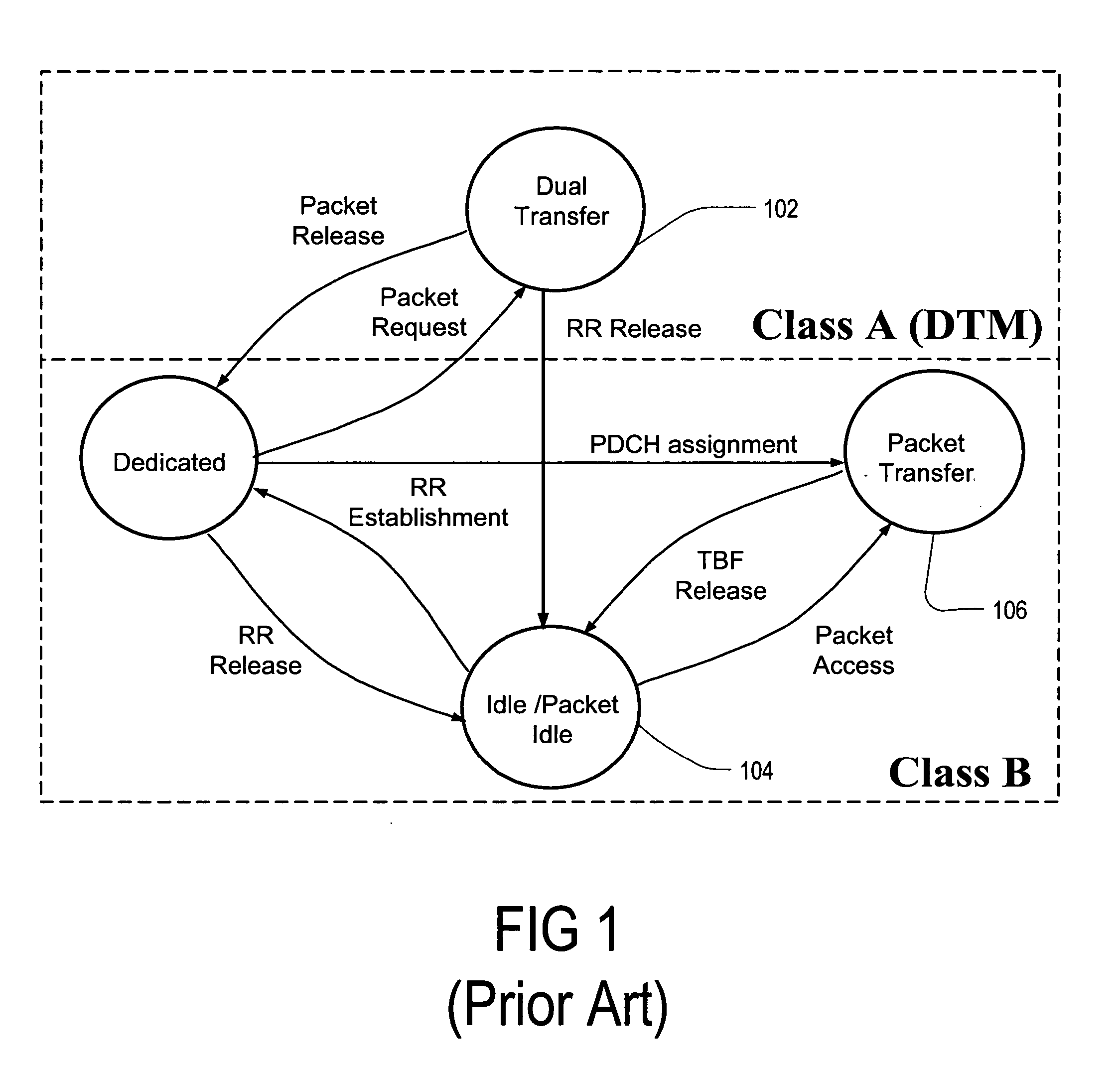
[0013] This invention has the advantage that the MS can maintain PS resources and gain better quality of service for a packet application. Gaps in PS service are minimized, especially if the MS has not changed location area during the CS connection. This invention thus allows an RR operation mode to be changed directly from dual transfer mode to the packet transfer mode without the release of packet resources after the release of an RR connection.
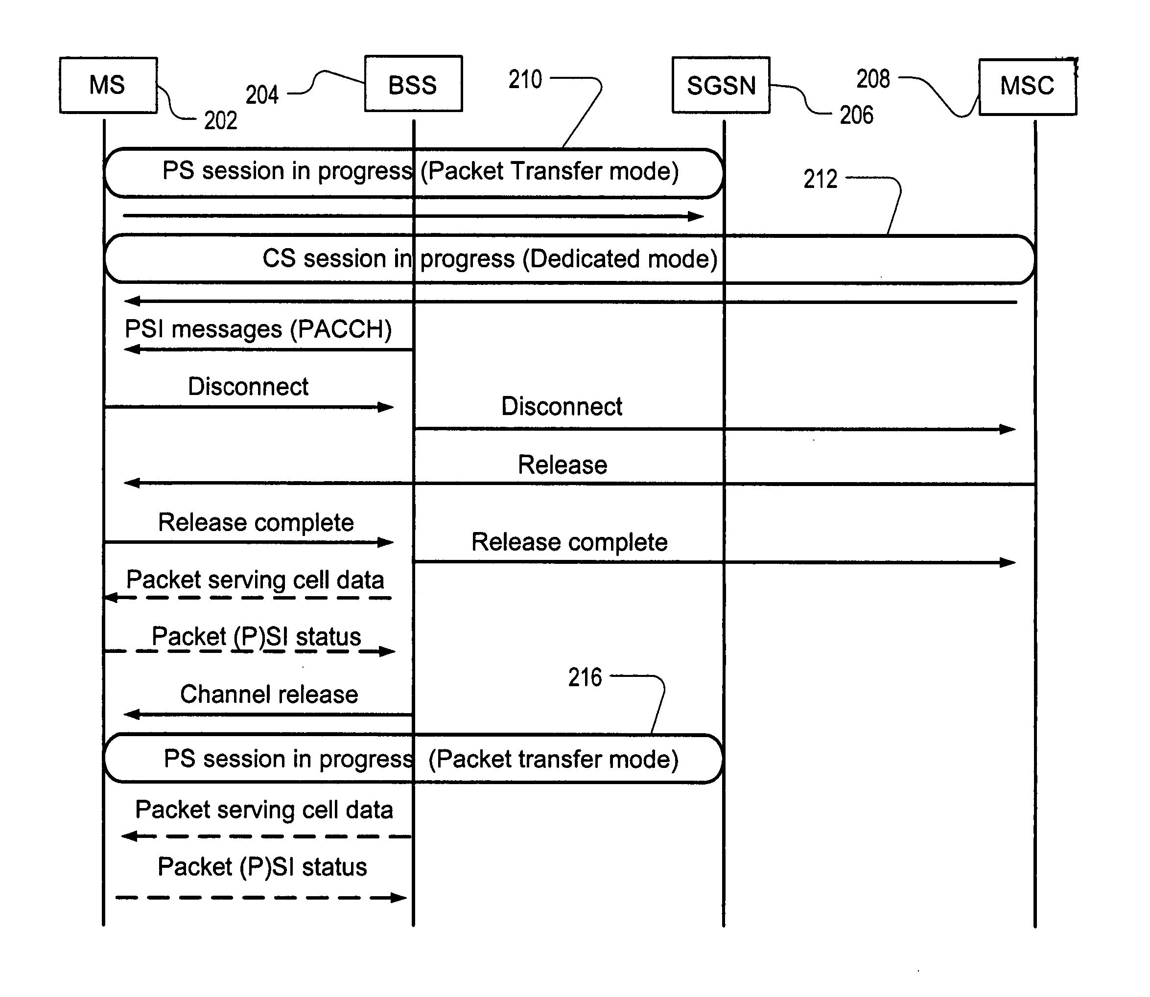
[0014] According to an embodiment of the present invention, a minimum system information (SI) or packet system information (PSI) is sent to the mobile station by using a packet serving cell data message before a circuit-switched channel is released. Thus, the mobile station will be able to immediately transition from dual transfer mode to packet transfer mode without having to request a packet-switched channel or resources.

Problems solved by technology

When the use of GSM data services started, it soon became evident that the Circuit Switched (CS) bearer services were not well-suited for certain types of applications with a bursty nature.
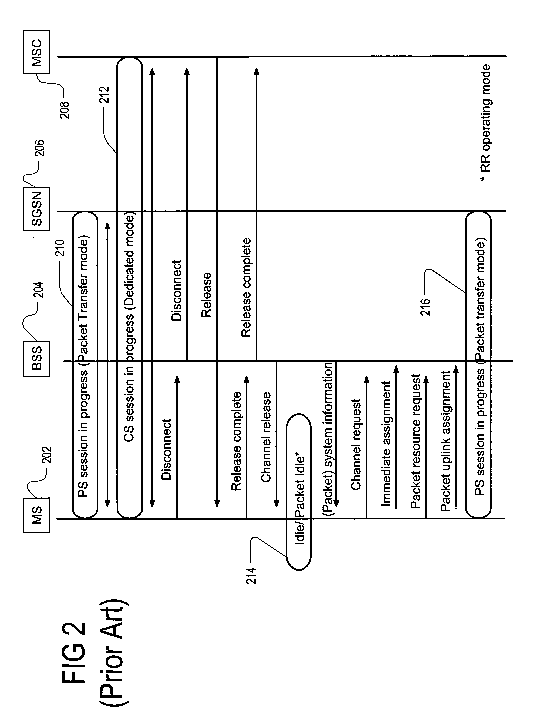
The main problem with these prior art techniques is that the MS is not allowed to immediately enter the packet transfer mode 216 until it has performed various steps.

Method used


Image

  • Enhancement of dual transfer mode when circuit switched resources are released
  • Enhancement of dual transfer mode when circuit switched resources are released
  • Enhancement of dual transfer mode when circuit switched resources are released

Examples


Embodiment Construction

[0020] The present invention describes a way to enhance the transition between two main situations: dual transfer mode, and packet transfer mode. Regarding action while in dual transfer mode, as mentioned previously, the MS obtains a certain set of system information depending on whether a packet control channel is supported or not by the network, in order to continue without a service gap in the packet transfer mode, after an RR connection is released. FIG. 3 depicts the enhanced transition from dual mode due to an RR connection release.

[0021] While in dual transfer mode the MS 202 may receive PSI messages on the packet associated control channel or PACCH (PBCCH exists on the cell). In 3GPP TS 44.060, “Radio Link Control / Medium Access Control (RLC / MAC) protocol,” it is specified that the MS shall check every 30 seconds whether the system information has been changed. This can also be a reasonable way for the MS to check for PSI messages received on the PACCH when in dual transfer ...


PUM


Abstract

A method and mobile terminal are disclosed for use in a wireless communication system in order for the mobile terminal to be able to transition from a dual mode, in which a packet switched connection and circuit switched connection are used together, to a single mode in which packets are transferred. The mobile terminal is for receiving minimum system information necessary to perform the transition in an uninterrupted manner, instead of an interrupted manner. This system information is broadcast to the mobile terminal on a regular basis, and is also sent to the mobile terminal partly or entirely by point-to-point transfer if a piece of the minimum system information is missing due to inadequate broadcast reception or some other reason. This system information is then employed by the mobile terminal to transition from the dual mode to the single mode in the uninterrupted manner.

Description

FIELD OF THE INVENTION [0001] The present invention relates to wireless communication, and more particularly to packet switching and circuit switching for wirelessly communicating with a mobile terminal. BACKGROUND OF THE INVENTION [0002] The first Global System for Mobile (GSM) communication networks were designed for voice services rather than for data services. When the use of GSM data services started, it soon became evident that the Circuit Switched (CS) bearer services were not well-suited for certain types of applications with a bursty nature. Therefore the new Packet Switched (PS) data transmission service GPRS (General Packet Radio Service) was developed for packet services. GPRS is a packet radio network utilizing the GSM network, and GPRS endeavours to optimize data packet transmission by means of GPRS protocol layers on the air interface between a mobile station (hereinafter also called a mobile terminal) and a GPRS network. [0003] A GPRS mobile station (MS) can operate ...

Claims


Application Information

Patent Timeline
IPC IPC(8): H04L12/28H04W36/06H04W76/04H04W76/06
CPCH04W36/0022H04W88/06H04W76/064H04W36/06H04W76/34H04W36/00224
Inventor VAITTINEN, RAMIKANGAS, ANTTI O.
Owner QUALCOMM INC
Learn More