Eureka AIR delivers breakthrough ideas for toughest innovation challenges, trusted by R&D personnel around the world.

Automotive fuel pump improvement

Inactive Publication Date: 2005-07-28
MORRIS R DAVID +1
View PDF12 Cites 7 Cited by
  • Summary
  • Abstract
  • Description
  • Claims
  • Application Information

AI Technical Summary

Benefits of technology

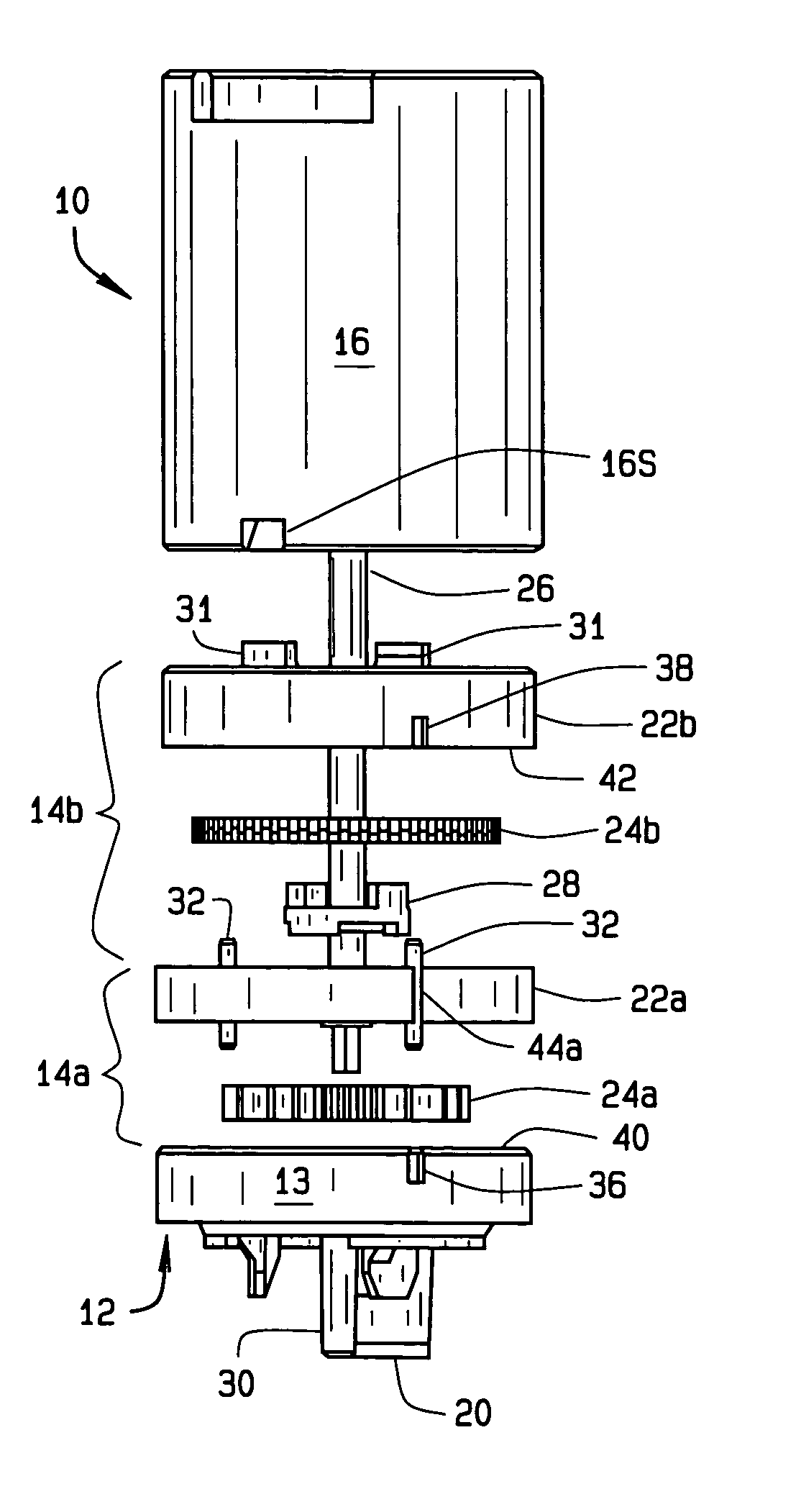
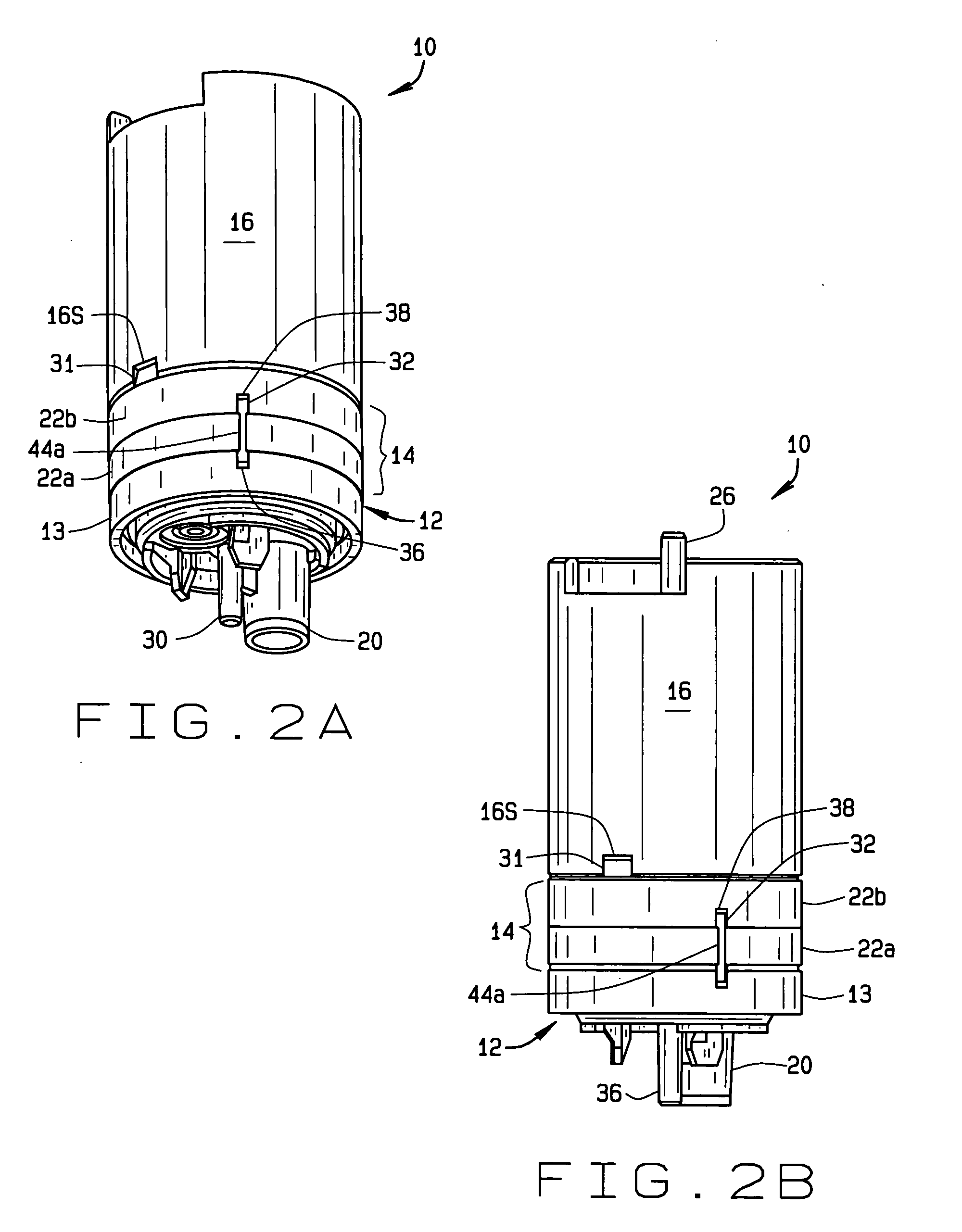
[0007] The present invention, briefly stated, is directed to a multi-stage turbine fuel pump for automotive vehicles. The fuel pump includes an inlet section through which low pressure fuel is drawn into the pump, a first pump stage and a second pump stage, and an outlet section through which high pressure fuel is discharged from the pump. Components comprising the respective first and second pump stages are aligned together by pins inserted in channels extending through the components to properly orient the parts. Each pin has a hollow, cylindrical shape with a longitudinal slot extending the length of the pin. The pins are made of a spring material, and each pin is compressed when the pump components are assembled together. The channels in each of the parts through which the pins are inserted comprise slots or pockets which open into the outer surface of the part. This construction helps distribute forces exerted by the pins against the sidewalls of the channels when the pump is subjected to shocks and vibrations, so to prevent the parts from cracking about the area where the channels are formed, weakening the parts.

Problems solved by technology

It has been that, over time, problems occur with each of these installations.
With threaded screws, vibrations and shocks to which the pump is subjected will tend to loosen the screws.
Even a slight loosening of the screws will affect pump performance since small gaps will appear between parts causing leakages which effect pumping efficiency.
With pins, the vibrations and shocks to which the pins are subjected are transmitted to the portion of the parts surrounding the pins, and will cause cracks to occur about the bores in these components.
This weakens these parts and can ultimately lead to their failure.
With the spring clips, alignment of the components is inconsistent and can result in low fuel flow through the pump and / or high amperage failures.

Method used


Image

  • Automotive fuel pump improvement
  • Automotive fuel pump improvement
  • Automotive fuel pump improvement

Examples


Embodiment Construction

[0019] The following detailed description illustrates the invention by way of example and not by way of limitation. This description will clearly enable one skilled in the art to make and use the invention, and describes several embodiments, adaptations, variations, alternatives and uses of the invention, including what I presently believe is the best mode of carrying out the invention. As various changes could be made in the above constructions without departing from the scope of the invention, it is intended that all matter contained in the above description or shown in the accompanying drawings shall be interpreted as illustrative and not in a limiting sense.

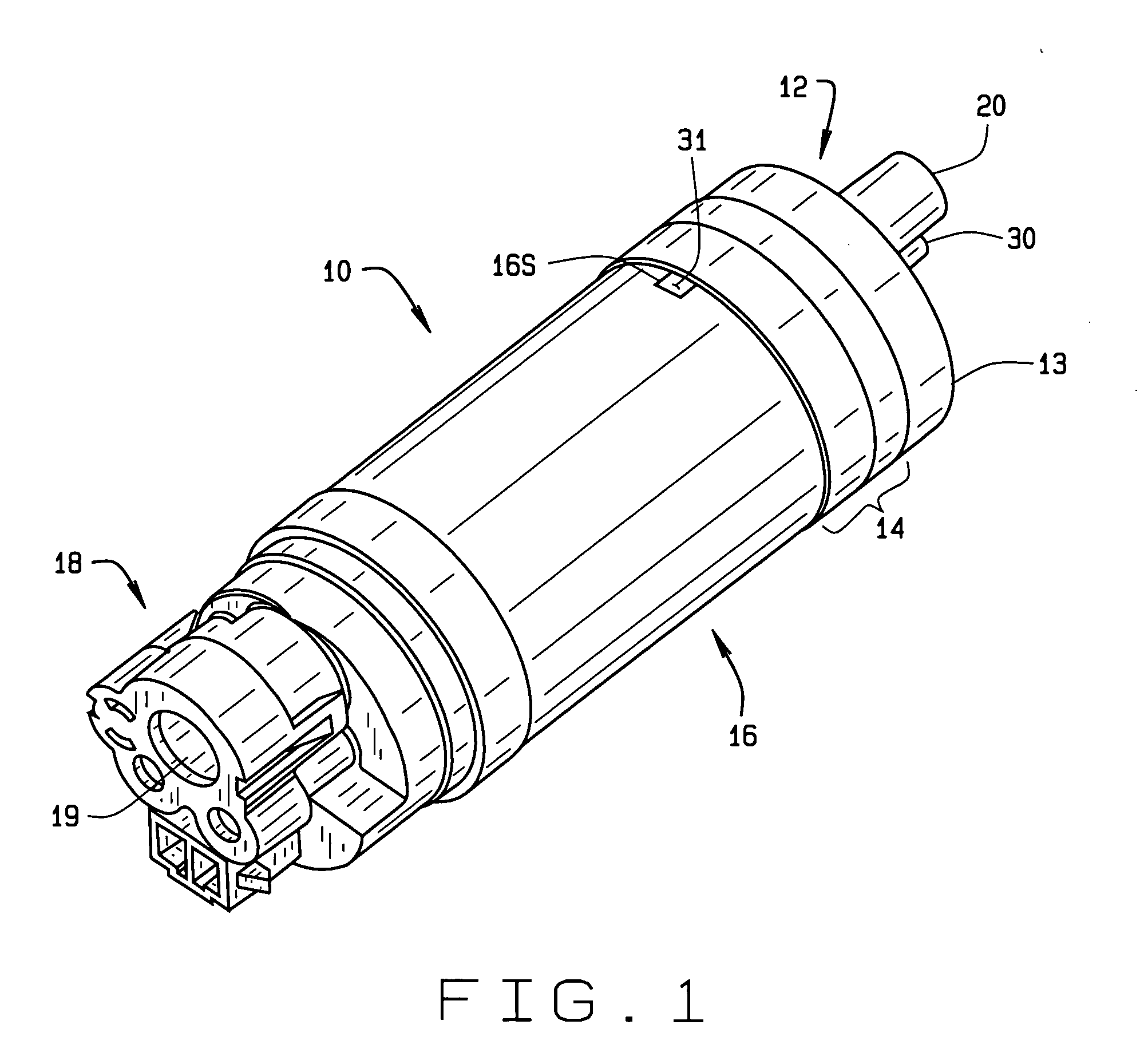
[0020] Referring to the drawings, an electric fuel pump for use with automotive vehicles is indicated generally 10. Pump 10 is a two-stage turbine pump having an inlet section 12, a fuel pumping section 14 including a first pump stage 14a and a second pump stage 14b, a housing 16 in which is housed a pump motor 17 (see FIG. ...


PUM


Abstract

A multi-stage turbine fuel pump (10) for automotive vehicles includes an inlet section (12) through which low pressure fuel is drawn into the pump, a first pump stage (14a) and a second pump stage (14b), and an outlet section (16) through which high pressure fuel is discharged from the pump. Components (13, 22a and 22b) comprising a pump inlet and respective first and second pump stages are aligned together by spring pins (32) inserted in open channels (36, 38, 44a and 44b) extending through the components so to improve fuel flow through the pump and prevent fuel leakage between the stages. Each pin has a hollow, cylindrical shape with a longitudinal slot (34) extending the length of the pin. The pins are made of a spring material, and each pin is compressed when inserted in place for the pin to thereafter press against a sidewall of the channel in which it is inserted, the force exerted by the pin on the channel sidewall maintaining alignment of the components.

Description

CROSS REFERENCE TO RELATED APPLICATIONS [0001] None STATEMENT REGARDING FEDERALLY SPONSORED RESEARCH OR DEVELOPMENT [0002] N / A BACKGROUND OF THE INVENTION [0003] This invention relates to electrical fuel pumps for use in automobiles and other vehicles; and more particularly, to a slotted spring pin and slot construction for aligning and holding components of the pump stages together and which prevents cracking of pump components in which the slots are formed so to prevent failure of a pump. [0004] Multi-stage fuel pumps for use in automotive vehicles are known in the art. The pump typically is a two-stage pump having a first and low pressure inlet stage followed by a second and high pressure outlet stage. The two pump stages, together with the electric motor driving the pump and the respective end caps in which inlet and outlet ports are formed must be accurately aligned during pump assembly in order for the pump to efficiently pump fuel from a tank to the engine in which the fuel i...

Claims


Application Information

Patent Timeline
IPC IPC(8): F04B3/00F04B5/00F04D5/00F04D29/62
CPCF04D29/628F04D5/006
Inventor MORRIS, R. DAVIDCARTER, LARRY R.
Owner MORRIS R DAVID
Why Eureka
Eureka Blog
Learn More