Waterbed Structure

a waterbed and structure technology, applied in the field of waterbed structures, can solve the problems of shortening the usage increasing the material cost to lower the practicability of the waterbed, and shortening the usage lifespan of the waterbed, so as to facilitate the filling of water, increase the length and area of the waterbed, and prolong the use life of the waterbed

Inactive Publication Date: 2005-08-04
CHOW ANDY S
View PDF3 Cites 3 Cited by
  • Summary
  • Abstract
  • Description
  • Claims
  • Application Information

AI Technical Summary

Benefits of technology

[0012] The primary object of the invention is to provide a waterbed structure having transverse pull strips at long air protection borders and attaching devices at all sides of a bed housing thereof, thereby preventing the air protection borders from expanding outward, and lengthening usage lifespan of the waterbed as well as appropriately increasing length and area of the waterbed as desired.
[0013] A waterbed structure according to the invention comprises a water-containing body, long air protection borders, and a bed housing having a frame-shaped protection accommodating chamber. The water-containing body is provided with a plurality of pull strip spacers, at least one water inlet plug and at least one air outlet plug, thereby facilitating a user to simultaneously fill in water and discharging air. Each of the long air protection borders is a longitudinal rectangular shape; and is devised with at least one air inlet plug at an appropriate position at an upper surface thereof, and transverse pull strips at a side thereof. The transverse strips have side edges thereof molded to side walls of the long air protection borders using high-cy

Problems solved by technology

Thus, material costs are increased to lower practicability of the water bed.
After a certain period of usage of the prior water bed structure, the air protection borders are likely to dilate to further shorte

Method used


Image

  • Waterbed Structure
  • Waterbed Structure
  • Waterbed Structure

Examples


Embodiment Construction

[0021] To better understand effects, structures and characteristics of the invention, a preferred embodiment shall be described with the accompanying drawings below.

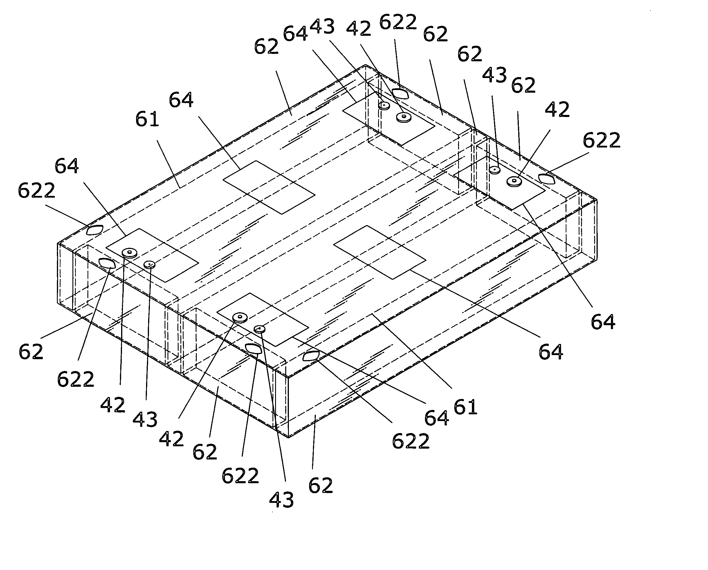
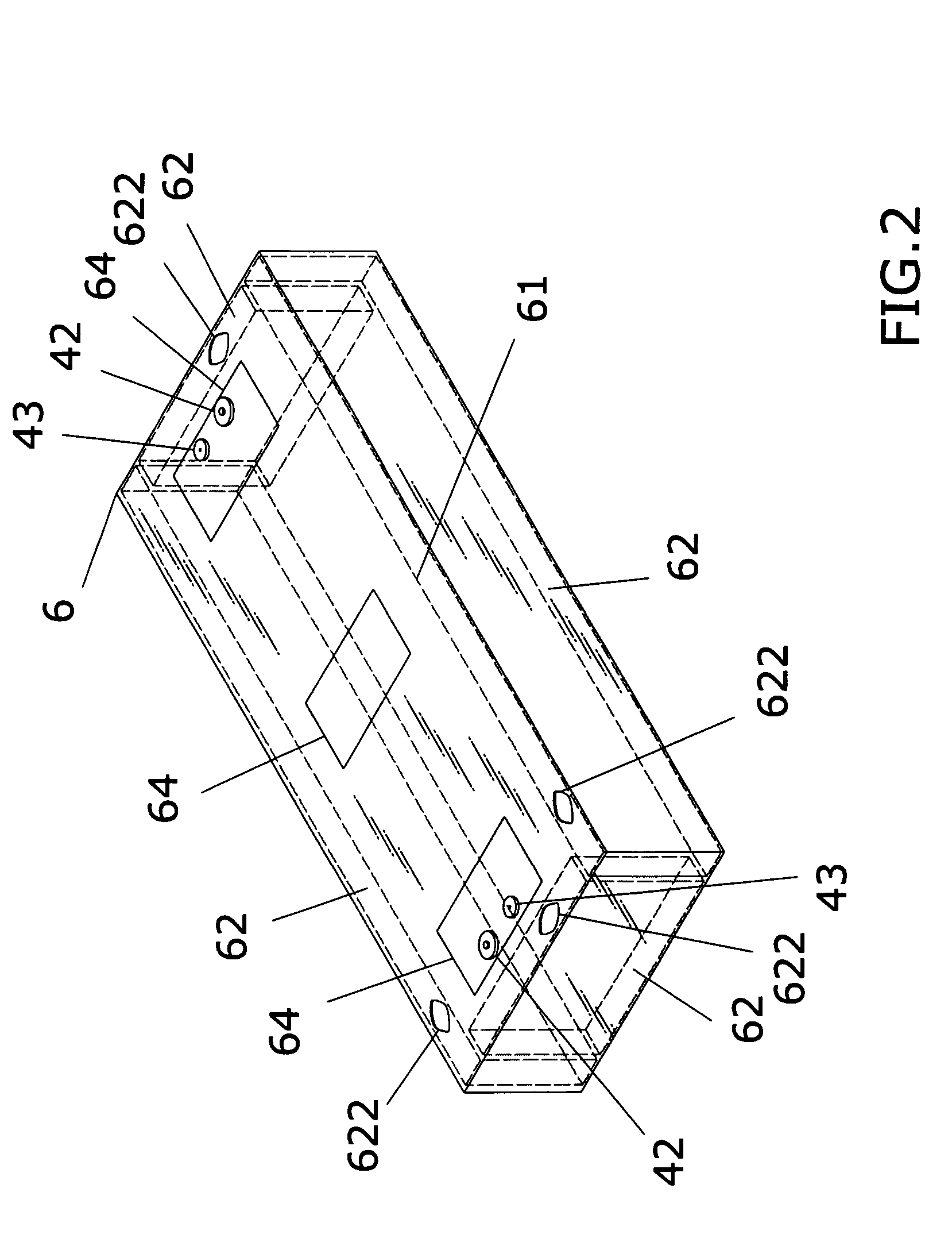
[0022] Referring to FIGS. 2 and 3 showing elevational schematic views of a waterbed structure as an embodiment according to the invention, the waterbed comprises a water-containing body 4, long air protection borders 5, and a bed housing 6 having a frame-shaped accommodating chamber. The water-containing body 4 is provided with a plurality of pull strip spacers 41, at least a water inlet plug 42 and at least a row of air outlet plugs43, so as to facilitate a user to simultaneously filling in water and discharging air.

[0023] Each of the long air protection strips 5 is a longitudinal rectangular shape as shown in FIG. 4. Each long air protection strip 5 is devised with at least one air inlet plug 51 at an appropriate position at an upper surface thereof, and transverse pull strips 52 at a side thereof. The transverse str...


PUM


Abstract

A waterbed structure according to the invention comprises a water-containing body, long air protection borders, and a bed housing having a frame-shaped protection accommodating chamber. Each of the long air protection borders has transverse pull strips at a side thereof. The transverse strips have side edges thereof molded to side walls of the long air protection borders using high-cycle heat, and are disposed at interiors of the long air protection borders. The bed housing has a frame-shaped protection accommodating chamber, which is provided with at least an aperture at an appropriate position at an inner or outer side thereof for placing the aforesaid long air protection border. Furthermore, the bed housing is devised with attaching devices for joining with a long air protection border, thereby preventing the air protection borders from expanding outward for lengthening usage lifespan of the waterbed.

Description

BACKGROUND OF THE INVENTION [0001] (a) Field of the Invention [0002] The invention relates to a waterbed structure, and more particularly, to a waterbed structure, which is capable of appropriately increasing a length of a bed body thereof as desired and preventing protective air protection borders thereof from expanding outward, thereby lengthening usage lifespan of the waterbed. [0003] (b) Description of the Prior Art [0004] Referring to FIG. 1 showing an elevational schematic view of a prior double waterbed, the prior waterbed comprises left and right water-containing bodies 1 and bed housing 2. Each of the water-containing body 1 has an outer layer 11; a water inlet plug 12 at an appropriate position of each outer layer 11 and for filling in water; a plurality of equidistant and parallel transverse pull strip spacers 13 that are loop-like and hollow structures; and a water opening 14 disposed at an appropriate position of each transverse pull strip spacer 13 and for allowing inj...

Claims


Application Information

Patent Timeline
IPC IPC(8): A47CA47C27/08A47C27/10
CPCA47C27/081A47C27/10A47C27/085
Inventor CHOW, ANDY S.
Owner CHOW ANDY S
Why Eureka
Try Eureka