Exhaust aftertreatment system universal joint flex pipe assembly

a technology of exhaust aftertreatment and flex pipe assembly, which is applied in the direction of mechanical equipment, machines/engines, transportation and packaging, etc., can solve the problems of relative movements, increasing vibrational stress, and increasing the harmfulness of certain stresses, so as to increase the useful life of the exhaust pipe and the exhaust system. , the effect of increasing the resistance to failur

Active Publication Date: 2021-08-19
PACCAR INC
View PDF6 Cites 0 Cited by
  • Summary
  • Abstract
  • Description
  • Claims
  • Application Information

AI Technical Summary

Benefits of technology

[0005]In view of these significant challenges as set forth above, which is not a complete list, it is desirable to provide a flexible pipe assembly that can reduce the stresses in an exhaust pipe to avoid failure in the exhaust pipe due to external stresses.
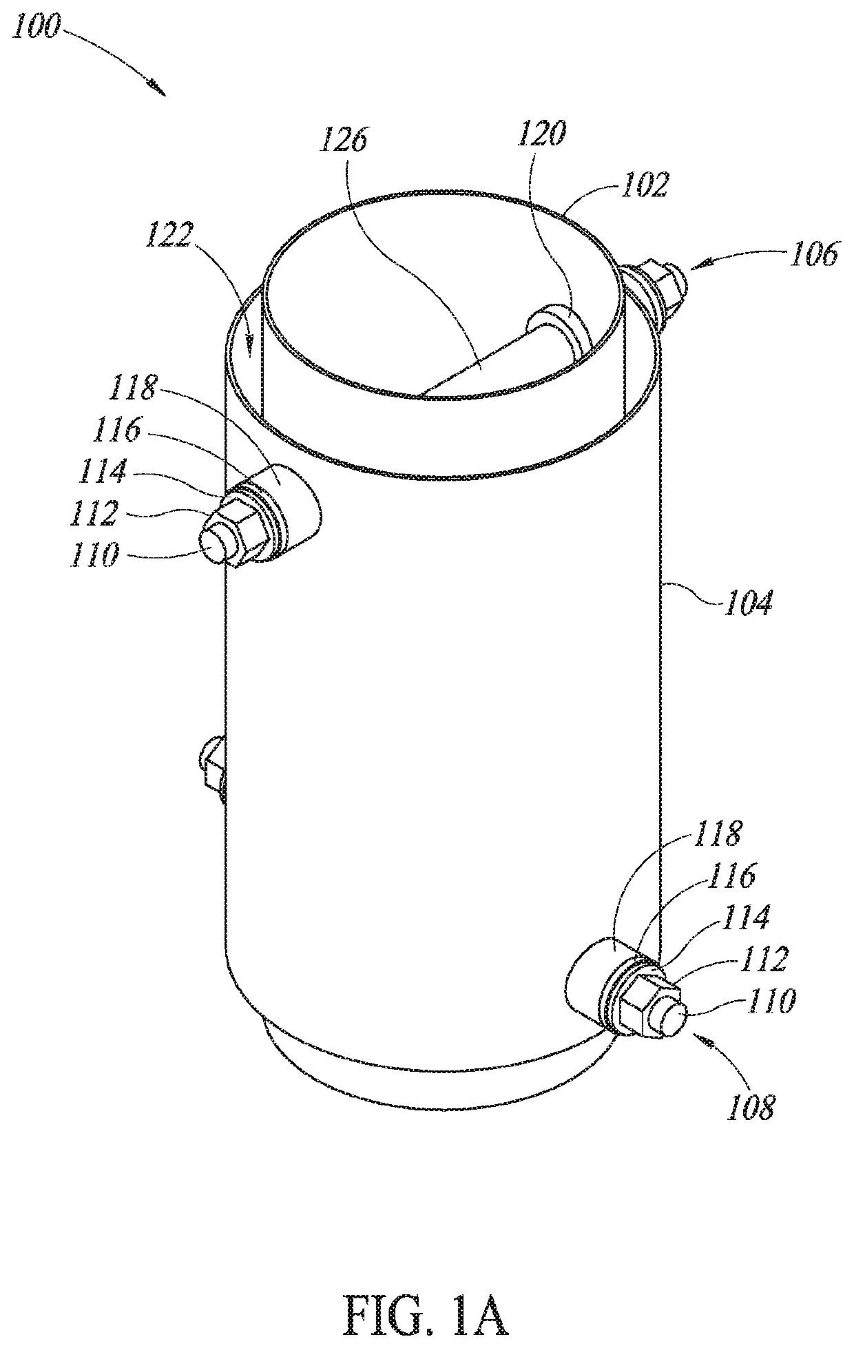
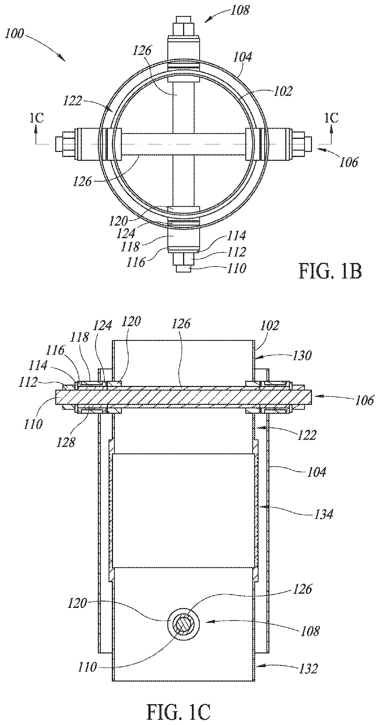
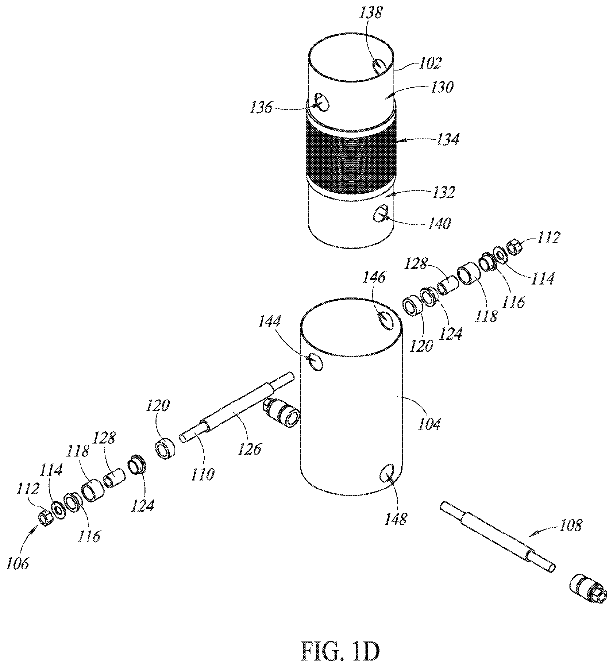
[0009]In certain embodiments, the pipe of the flexible pipe assembly that is positioned within the sleeve of the flexible pipe assembly may include a first end portion, a second end portion, and a bellows. The bellows is configured to allow flexing, bending, and deformation in the pipe to increase resistance against failure in the exhaust pipe system due to relative movement between a chassis and a cab of the truck when in use. The bellows may be a torsional bellows, a wrapped spiral bellows, a mesh bellows, a traditional bellows, an accordion bellows, a straight bellows, or any other bellows as desired that is configured to allow the flexible pipe assembly to flex, bend, or be displaced in a manner to allow the exhaust pipe and flexible pipe assembly to adjust, flex, bend, and deform in response to the relative movement between the chassis and the cab of the truck when in use, which increases the useful lifespan of the exhaust pipe and exhaust system.

Problems solved by technology

As requirements and demands to reduce emissions of vehicles and trucks within the vehicle and truck industries increases and use of EAS becomes more common, manufacturers face significant challenges to provide exhaust systems that can resist and withstand vibrational stresses such as resonance frequencies or a natural frequencies of various components that the various components are exposed to when a vehicle or truck is in use.
This is especially true when the EAS is secured and mounted to a vehicle chassis and an exhaust pipe is secured and mounted to the EAS and is secured and mounted to a cab of the vehicle because the vehicle chassis and cab move relative to each other, which causes vibrational stresses that may be close to natural frequencies of various components within the vehicle or truck.
These bends in the exhaust pipe and coupling between the exhaust pipe and the outlet are points at which failure is likely to occur when the truck is being driven because of external stresses caused by vibration, external forces, or relative movement between the chassis and cab when the vehicle or truck is in use.
Other points of failure include points where the exhaust pipe is mounted to the cab and points where the EAS is mounted to the vehicle chassis.
However, if the exhaust pipe is mounted too loosely or provided too many degrees of freedom, the harmfulness of certain stresses and relative movements can increase substantially if low stiffness of the exhaust pipe results in excessive movement or resonance when the exhaust pipe is exposed to the operating environment of the vehicle.
Likewise, if the exhaust pipe is mounted too rigidly, the harmfulness of relative movements between the chassis and cab of the truck increases substantially.
Accordingly, it is a significant challenge to provide an exhaust system having a low stiffness in certain degrees of freedom, which allow for relative movement between connection points on the cab and the chassis, while maintaining a high stiffness in other degrees of freedom to prevent excessive movement or modal resonance with the vibrations present in the operating environment of the vehicle is desired.

Method used


Image

  • Exhaust aftertreatment system universal joint flex pipe assembly
  • Exhaust aftertreatment system universal joint flex pipe assembly
  • Exhaust aftertreatment system universal joint flex pipe assembly

Examples


Embodiment Construction

[0024]In the following description, certain specific details are set forth in order to provide a thorough understanding of various embodiments of the disclosure. However, one skilled in the art will understand that the disclosure may be practiced without these specific details.

[0025]Unless the context requires otherwise, throughout the specification and claims that follow, the word “comprise” and variations thereof, such as “comprises” and “comprising,” are to be construed in an open, inclusive sense, that is, as “including, but not limited to.”

[0026]The use of ordinals such as first, second and third does not necessarily imply a ranked sense of order, but rather may only distinguish between multiple instances of an act or structure.

[0027]Reference throughout this specification to “one embodiment” or “an embodiment” means that a particular feature, structure or characteristic described in connection with the embodiment is included in at least one embodiment. Thus, the appearances of...


PUM


Abstract

The present disclosure is directed to a flexible pipe assembly that includes a pipe, a sleeve, a first connection assembly, and a second connection assembly. The pipe of the flexible pipe assembly includes a first end portion that is coupled to an external vertical exhaust pipe that allows exhaust to escape from a truck and a second end portion that is coupled to a pipe to an outlet of an exhaust aftertreatment system (EAS). The pipe also includes a third portion, which is a bellows, coupling the first end portion to the second end portion of the pipe of the flexible pipe assembly. The first and second connection assemblies couple the sleeve to the pipe of the flexible pipe assembly by passing through holes in the sleeve and the pipe of the flexible pipe assembly.

Description

BACKGROUNDTechnical Field[0001]The present disclosure relates to a pipe assembly coupling an exhaust aftertreatment system (EAS) that is coupled to an exhaust outlet of an engine of a vehicle to an exhaust pipe of the vehicle.Description of the Related Art[0002]As requirements and demands to reduce emissions of vehicles and trucks within the vehicle and truck industries increases and use of EAS becomes more common, manufacturers face significant challenges to provide exhaust systems that can resist and withstand vibrational stresses such as resonance frequencies or a natural frequencies of various components that the various components are exposed to when a vehicle or truck is in use. This is especially true when the EAS is secured and mounted to a vehicle chassis and an exhaust pipe is secured and mounted to the EAS and is secured and mounted to a cab of the vehicle because the vehicle chassis and cab move relative to each other, which causes vibrational stresses that may be close ...

Claims


Application Information

Patent Timeline
Patent Type & Authority Applications(United States)
IPC IPC(8): F01N13/18B62D33/06
CPCF01N13/1816F01N13/1822B62D33/06F01N13/1855F01N2450/24F01N2470/24F01N2590/08
Inventor BUNDY, ROBERT LEEPARK, JAMES NOAH
Owner PACCAR INC
Why Eureka
Try Eureka