Method for indexing a rotating tool and a tool for machining

a technology of which is applied in the field of indexing rotating tools and machining tools, can solve the problems of not always enough space in the tool magazines of machine tools for all different tools, only one fixed measure of the tool, and inability to change the tool in the machine tool, etc., to achieve easy creation of sufficiently strong fastening forces, good blowing and vibration, and accurate dimensional accuracy

Inactive Publication Date: 2005-08-04
MANDREL OY
View PDF21 Cites 22 Cited by
  • Summary
  • Abstract
  • Description
  • Claims
  • Application Information

AI Technical Summary

Benefits of technology

[0009] An advantage of the invention is that the cutting part of the tool can be indexed and locked into predetermined positions with normal functions of the machine tools and without electric or the like external means. Accordingly, the tool according to the invention can be arranged in a conventional machine tool without any special accessories or essential variations. In addition, a pressure medium operated actuator endures well blows and vibration. Furthermore, such an actuator can be used to relatively easily create sufficiently strong fastening forces, rendering the tool solid and dimensionally accurate.

Problems solved by technology

Consequently, such a tool has only one fixed measure that can no longer be changed in the machine tool.
The problem herein is that the number of tools becomes large.
However, there is not always sufficiently space in the tool magazines of machine tools for all different tools, not to mention reserve tools.
This presents a significant drawback particularly in automatic machine tools intended for unmanned drive.
Furthermore, much time is taken by change of tools when machining with a tool having a special form, since a special tool, set to one measure, has to be retrieved for each measure machined, which naturally impairs the performance of machining.
However, one of the drawbacks is that the electric conductor has to be led to the rotating tool through the spindle.
Consequently, an electrically controlled tool is subject to significant changes in conventional machine tools.
Furthermore, an electrically controlled tool is susceptible to malfunction under demanding machine shop circumstances.
A further drawback of an electrically adjustable tool is its high price.

Method used


Image

  • Method for indexing a rotating tool and a tool for machining
  • Method for indexing a rotating tool and a tool for machining
  • Method for indexing a rotating tool and a tool for machining

Examples


Embodiment Construction

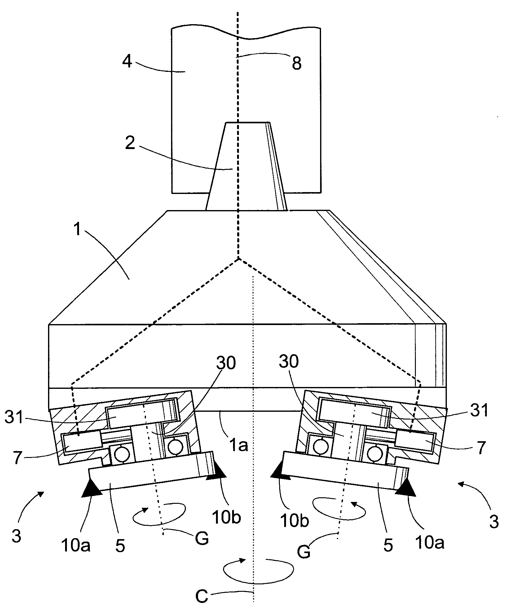
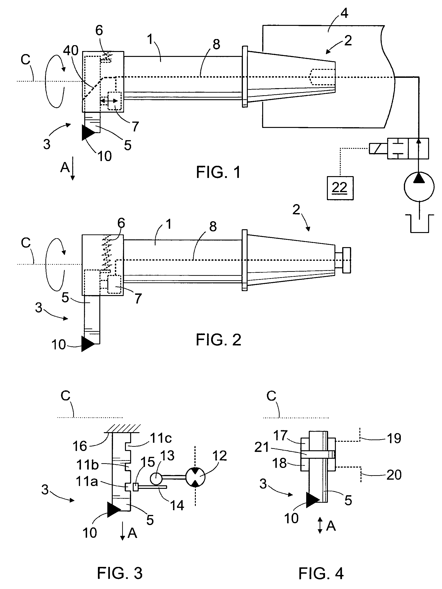
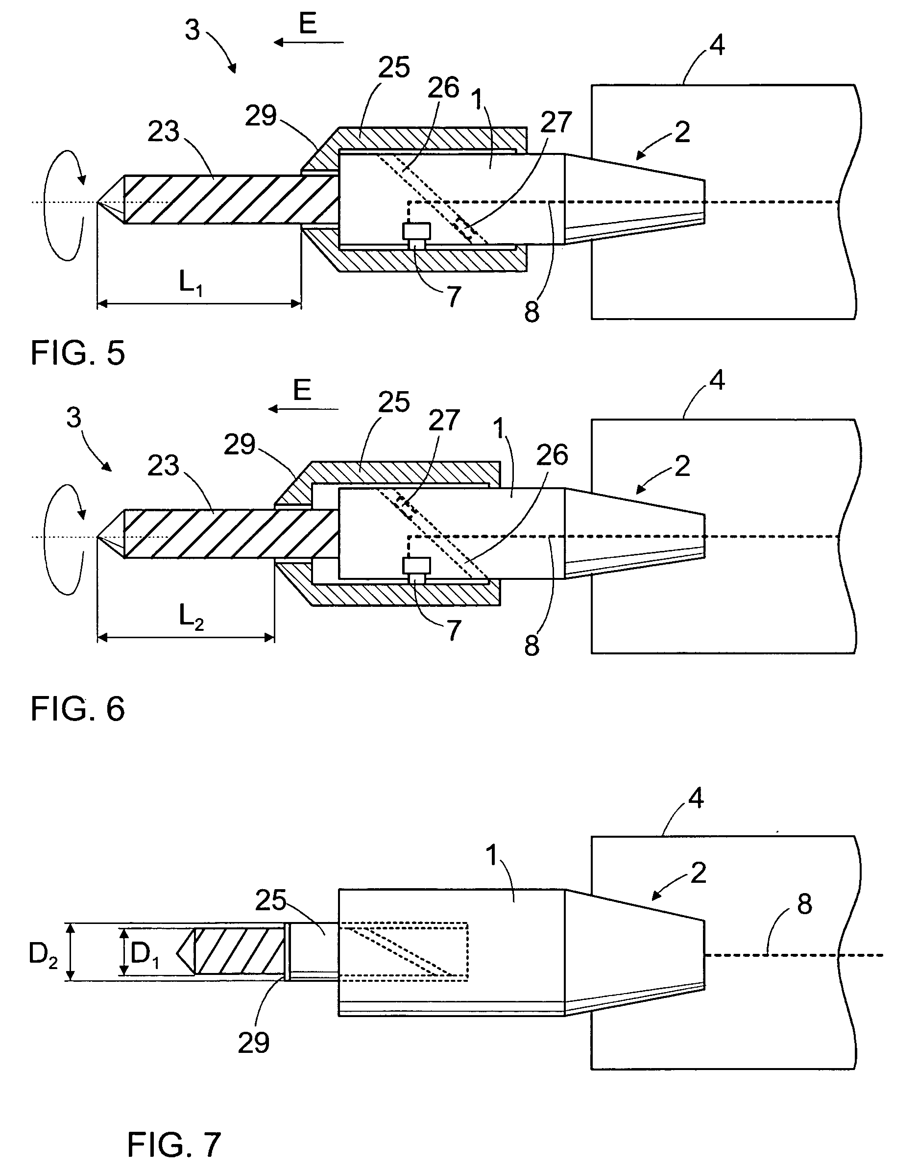
[0024]FIG. 1 shows a boring tool comprising a body 1, a fastening part 2 at one end of the body 1, and a cutting part 3 at the other end of the body 1. There may be one or several cutting parts 3. The fastening part 2 may comprise a taper or other suitable means for fastening the tool to a spindle 4 in a machine tool. Furthermore, the fastening part 2 may be a separate piece detachable from and attachable to the body 1. FIG. 2 shows the principle of an alternative fastening part 2. On the other hand, the fastening part 2 may refer to a contact surface in the body 1 of the tool, to which one or more pieces can be fastened for fastening the tool to the spindle 4 of the machine tool. When the spindle 4 is rotated, the tool, arranged in the spindle 4, rotates around its longitudinal axis C. The cutting part 3 may comprise an elongated insert holder 5 and an insert 10 fastened thereto. The insert 10 is an interchangeable part made from a highly durable material and comprising at least on...


PUM

PropertyMeasurementUnit
movementsaaaaaaaaaa
pressureaaaaaaaaaa
moments of inertiaaaaaaaaaaa

Abstract

A method of indexing a rotating cutting tool, and a tool for machining. The tool comprises a body, and one or more cutting parts, of which cutting parts at least one can be moved relative to the body at least into a first position and a second position. The cutting part is locked into the indexed positions by means of a pressure medium operated actuator.

Description

[0001] This application is a Continuation of International Application PCT / FI2003 / 000518 filed on 26 Jun. 2003, which designated the U.S. and was published under PCT Article 21(2) in English.FIELD OF THE INVENTION [0002] The invention relates to a method of indexing a rotating tool used in machining, and further to a tool for machining. The tool is rotated around its axis in a spindle of a machine tool, and at least one cutting part comprised by the tool is indexed relative to a body of the tool in such a manner that the cutting part has at least a first position and a second position. BACKGROUND OF THE INVENTION [0003] Different machine tools are used in machining, such as milling machines, horizontal boring and milling machines and drilling machines. Lathes may also comprise rotating tools. Machine tools comprise a spindle, in which a tool can be arranged, which can be made to rotate around its axis by rotating the spindle. The tool comprises a body having fastening means for fast...

Claims


Application Information

Patent Timeline
Patent Type & Authority Applications(United States)
IPC IPC(8): B23B3/00B23B29/034B23B51/04B23B51/10B23C5/00B23C5/20B23Q1/28B23Q11/10B23Q16/04B23Q16/08
CPCB23B29/03403Y10T82/2587B23B51/108B23B2260/004B23B2270/025B23B2270/04B23C5/006B23C5/20B23Q11/10B23Q16/04Y10T408/455Y10T82/128Y10T408/85Y10T82/10B23B51/0426B23Q1/287B23Q16/08
Inventor PELTONEN, KALLEREINIKKA, MARKUS
Owner MANDREL OY
Why Eureka
Try Eureka