Coupling valve structure for fuel supply module

Inactive Publication Date: 2005-08-04
CONTINENTAL AUTOMOTIVE SYST INC
View PDF35 Cites 5 Cited by
  • Summary
  • Abstract
  • Description
  • Claims
  • Application Information

AI Technical Summary

Benefits of technology

[0006] An object of the invention is to fulfill the need referred to above. In accordance with the principles of the present invention, this objective is achieved by providing a structure for a fuel supply module. The module has a fuel pump disposed in a fuel reservoir, a feed line in fluid communication with an outlet of the fuel pump for feeding fuel to an engine or high pressure fuel pump, and a return line for retuning excess fuel from the engine to the reservoir. The structure includes a check valve constructed and arranged to communicate with the feed line to permit fuel to be delivered to the engine and to prevent the fuel from draining back to the fuel pump, and a pressure relief valve integrally connected with the check valve via a conduit. The pressure relief valve is constructed and arranged to communicate with the return line such that when pressure of the fuel at the check valve is outside a certain pressure range, the pressure relief valve will open to permit fuel in the conduit to enter the return line to thereby maintain fuel exiting the check valve within the certain pressure range.
[0007] In accordance with another aspect of the invention, a fuel supply system is provided for delivering fuel to an engine. The system includes a fuel reservoir constructed and arranged to be mounted in a fuel tank, a fuel pump disposed in the fuel reservoir, a high pressure pump constructed and arra

Problems solved by technology

The use of a separate check valve and regulator increases the part co

Method used


Image

  • Coupling valve structure for fuel supply module
  • Coupling valve structure for fuel supply module
  • Coupling valve structure for fuel supply module

Examples


Embodiment Construction

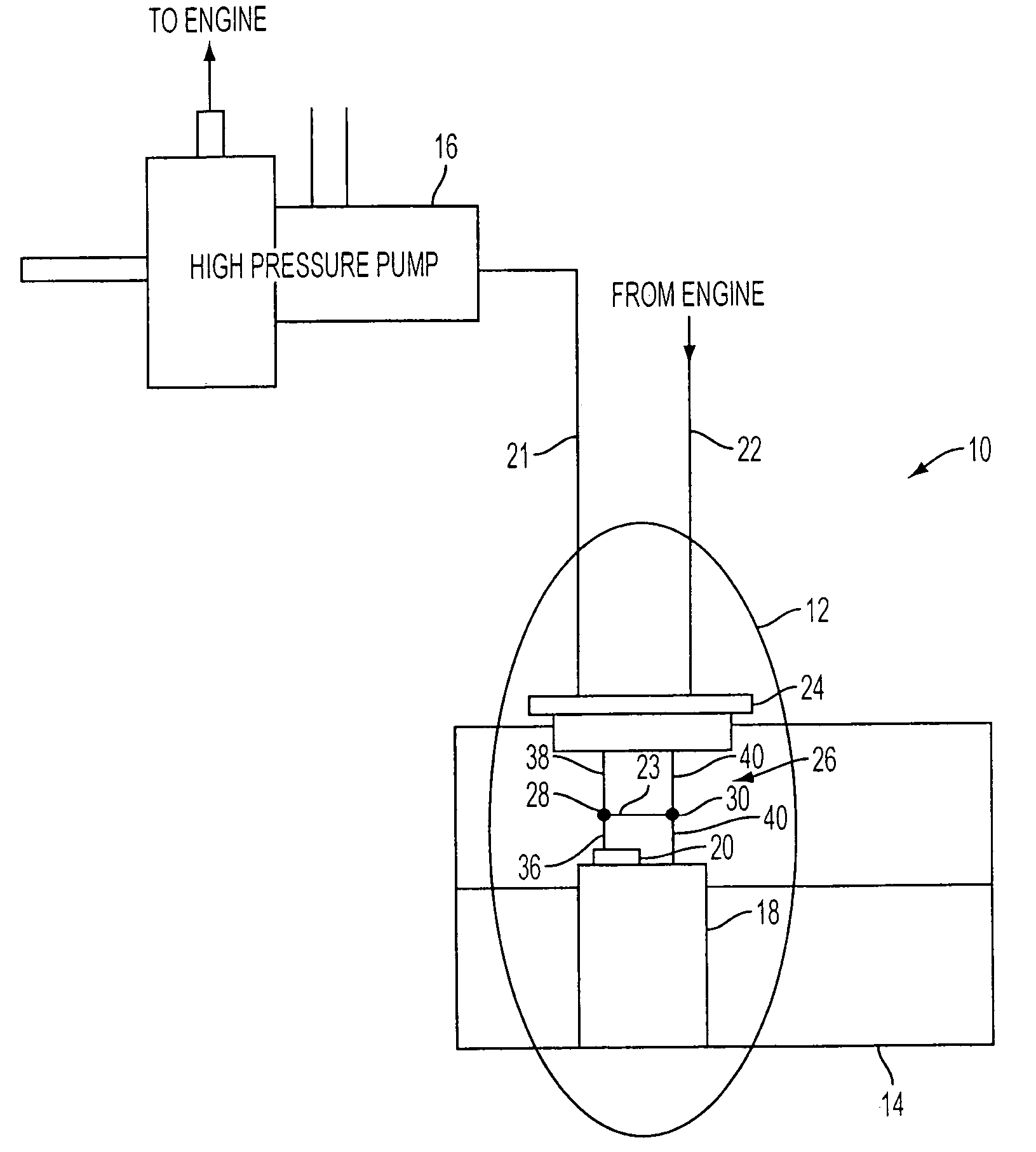
[0014] With reference to FIG. 1, a fuel supply system, generally indicated at 10, includes fuel supply module encircled at 12, contained inside a fuel tank 14, and high pressure pump 16, which is external to fuel tank 14. Operationally, fuel from tank 14 enters a reservoir 18 of module 12 and is pumped, via fuel pump 20, to the high pressure pump 16, via a feed line 21. The high-pressure pump delivers fuel into an engine (not shown). Fuel that is not used by engine or the high pressure fuel pump returns to the reservoir 18 via a return line 22. Module 12 thus includes the reservoir 18, the fuel pump 20, a flange 24 and, in accordance with the principles of the invention, coupling valve structure, generally indicated at 26.

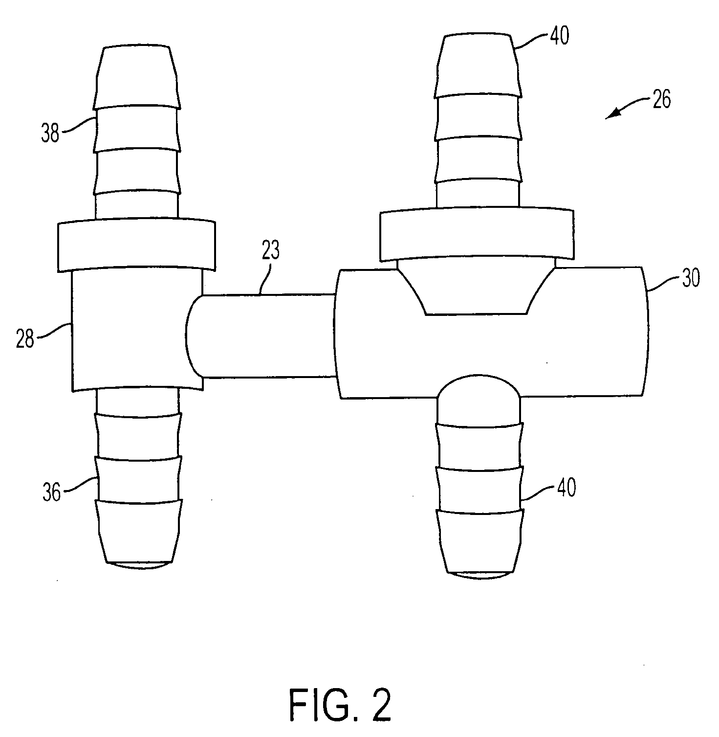
[0015] With reference to FIG. 2, the coupling valve structure 26 is preferably a one-piece structure that is located between the flange 24 and reservoir 18. As best shown in FIG. 3, the coupling valve structure 26 includes a check valve 28 integrally connected wit...


PUM


Abstract

A coupling valve structure 26 is provided for a fuel supply module 20. The module has a fuel pump 20 disposed in a fuel reservoir 18, a feed line 21 in fluid communication with an outlet of the fuel pump for feeding fuel to a high pressure pump 16 and thus to an engine, and a return line 22 for retuning excess fuel from the engine or high pressure fuel pump to the reservoir 18. The coupling valve structure 26 includes a check valve 28 constructed and arranged to communicate with the feed line to permit fuel to be delivered to the engine and to prevent the fuel from draining back to the fuel pump, and a pressure relief valve 30 integrally connected with the check valve via a conduit 23. The pressure relief valve 30 is constructed and arranged to communicate with the return line such that when pressure of the fuel at the check valve 28 is outside a certain pressure range, the pressure relief valve will open to permit fuel in the conduit to enter the return line to thereby maintain fuel exiting the check valve within the certain pressure range.

Description

[0001] This Application is based on U.S. Provisional Application No. 60 / 540,541, filed on Jan. 30, 2004, and claims the benefit thereof for priority purposes.FIELD OF THE INVENTION [0002] This invention relates to fuel supply module for vehicles and, more particularly, to a coupling valve structure that incorporates a check valve and pressure relief valve. BACKGROUND OF THE INVENTION [0003] Conventional fuel supply modules include a fuel pump in a reservoir that is mounted in a fuel tank. A fuel supply line is provided to deliver fuel pumped by the fuel pump to an engine or a high-pressure fuel pump. Typically, a check valve is provided in a fuel supply line to prevent fuel from returning to the reservoir. In addition, a separate regulator or pressure relief valve is typically provided in another part of the fuel supply line to ensure that fuel is delivered to the engine at a predetermined pressure. [0004] The use of a separate check valve and regulator increases the part count, ass...

Claims


Application Information

Patent Timeline
IPC IPC(8): F02M37/00F02M37/10F02M55/00
CPCF02M37/0023F02M37/0029F02M55/00F02M37/106F02M37/0052F02M37/00F02M59/44
Inventor SCHMITT, JOCHENDILCHERT, HOLGERTEICHERT, MICHAELBERNERT, ANDREAS
Owner CONTINENTAL AUTOMOTIVE SYST INC
Why Eureka
Try Eureka