Multi-tube heat exchanger

Inactive Publication Date: 2005-08-04
JAPAN STEEL WORKS LTD
View PDF10 Cites 19 Cited by
  • Summary
  • Abstract
  • Description
  • Claims
  • Application Information

AI Technical Summary

Benefits of technology

[0009] The invention has been made in view of the above described circumstances as the background, and it is an object of the invention to provide a multi-tube heat exchanger in which tubes can be stably fixed wit

Problems solved by technology

However, in the heat exchanger in which the small pass holes are formed in the baffle plate, there has been a problem that the fluid cannot favorably pass through the small pass holes due to their insufficient opening rate, and a request for lowering the fluid resistance cannot be fully satisfied.
Moreover, in the heat exchanger in which the metal plates are assembled like a latticework, although the fluid can relatively favorably flow, supporting strength for the tubes is insufficient, and therefore, it is necessary to employ the metal plates having a larger width (in th

Method used


Image

  • Multi-tube heat exchanger
  • Multi-tube heat exchanger
  • Multi-tube heat exchanger

Examples


Example

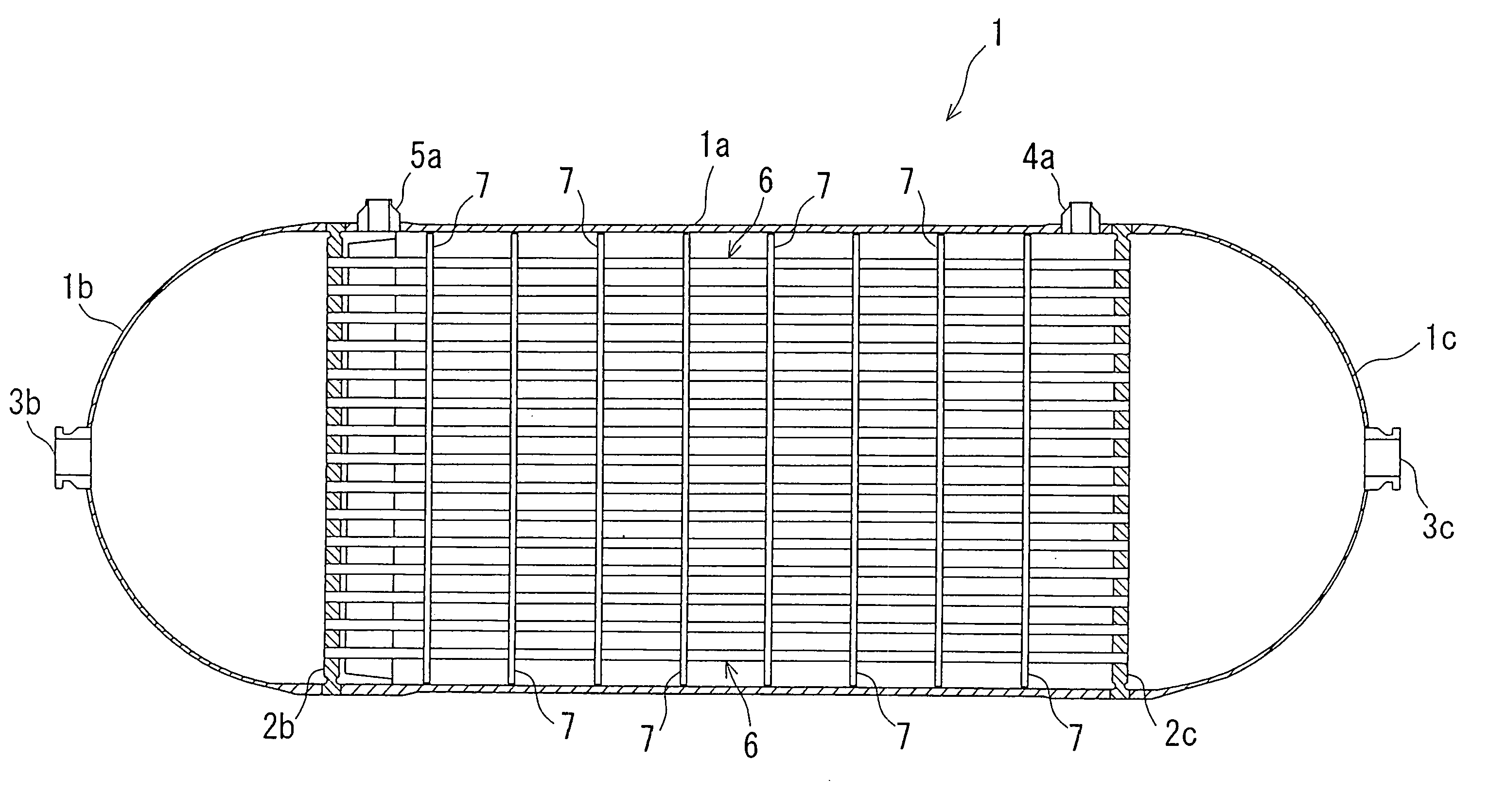
[0024] Now, an embodiment of the invention will be described referring to FIGS. 1 and 2A and 2B.

[0025] An outer shell 1 mainly includes a body part 1a in a cylindrical shape, and head parts 1b, 1c in a semicircular shape which are continued from both ends of the body part la. Inside the outer shell 1, there are provided partition walls 2b, 2c for separating a space inside the body part 1a from spaces inside the head parts 1b, 1c. The head parts 1b, 1c are respectively provided with fluid ports 3b, 3c which are open to the exterior and communicated with the spaces defined by the partition walls 2b, 2c. The body part 1a is provided with fluid ports 4a, 5a which are open to the exterior and communicated with the spaces defined by the partition walls 2b, 2c.

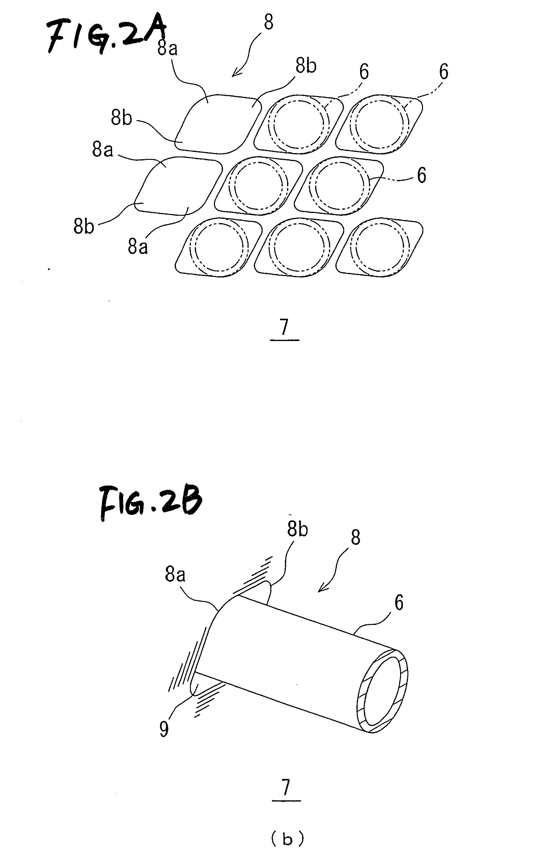
[0026] Further, a number of tubes 6 bundled into a tube bundle are bridged between the partition walls 2b, 2c. Both ends of the tubes are respectively communicated with the spaces inside the head parts 1b, 1c which are defined by t...


PUM


Abstract

The multi-tube heat exchanger includes a bundle of tubes which form fluid passages of first heat exchanging fluid, an outer shell which covers the bundle of tubes and form a fluid passage of second heat exchanging fluid, and a baffle plate which is arranged inside the outer shell in a direction intersecting an axial direction of the bundle of tubes and provided with a plurality of through holes through which respective tubes of the bundle are passed. Each of the through holes has such a shape that a portion of an outer peripheral face of the tube comes into contact with a portion of an inner peripheral face of the through hole, and a gap for passing the second heat exchanging fluid is formed between the other portion of the inner peripheral face and the outer peripheral face of the tube. It is possible to support the tubes with high dimensional accuracy, and to enhance heat exchanging efficiency by decreasing fluid resistance. It is also possible to make pitch of the through holes smaller and to make the heat exchanger compact.

Description

BACKGROUND OF THE INVENTION [0001] 1. Field of the Invention [0002] The present invention relates to a multi-tube heat exchanger for saving energy in plants of various types, architectures and so on, or for conducting chemical reactions, and more particularly to a structure of a baffle plate which is employed in the multi-tube heat exchanger. [0003] 2. Related Art [0004] As a type of heat exchanger structure, there has been known a multi-tube heat exchanger. This type of heat exchanger includes a number of tubes bundled into a tube bundle which are arranged inside an outer shell, and heat exchanging fluids having respectively different temperatures are supplied into the multi-tubes and inside the outer shell, thereby to conduct heat exchange between the heat exchanging fluids through walls of the multi-tubes. There have been known some types of this heat exchanger in which a baffle plate is provided at the right angle with respect to an axial direction of the tubes for the purpose o...

Claims


Application Information

Patent Timeline
IPC IPC(8): F28D7/16F28F9/02F28F9/013F28F9/22F28F9/24
CPCF28F9/22F28D7/16F28F9/24
Inventor OZEKI, YOSHIHISANARITA, ATSUSHIISOGAI, HIDEKAZUKUNAI, ICHIROKAYANO, RINZOINOUE, SAKIO
Owner JAPAN STEEL WORKS LTD
Why Eureka
Try Eureka