
Panel cutting jig

a cutting jig and panel technology, applied in the direction of clamping devices, sawing devices, gripping devices, etc., can solve the problem of uneven cutting surface of wood panels

Pending Publication Date: 2022-07-28
RICO BLINDS CO LTD
View PDF6 Cites 0 Cited by
  • Summary
  • Abstract
  • Description
  • Claims
  • Application Information

AI Technical Summary

Benefits of technology

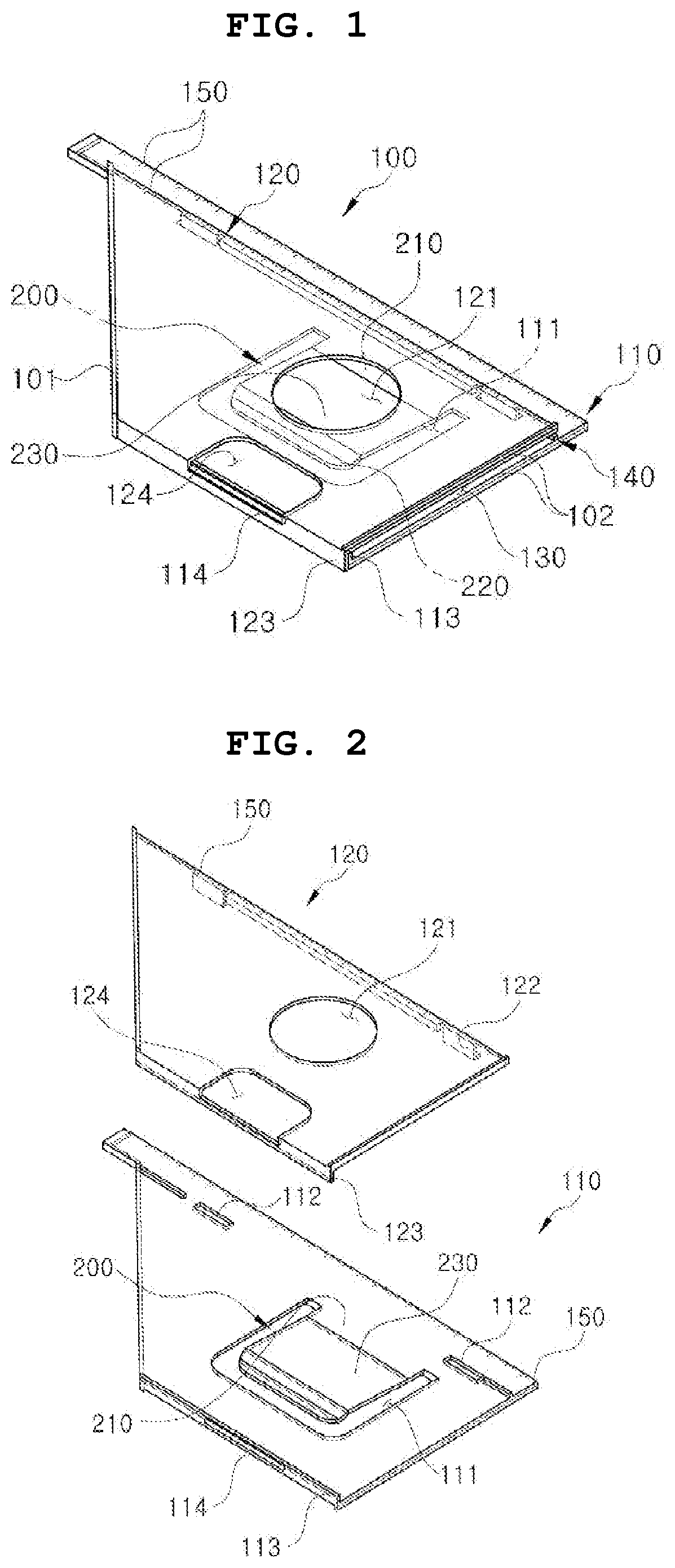
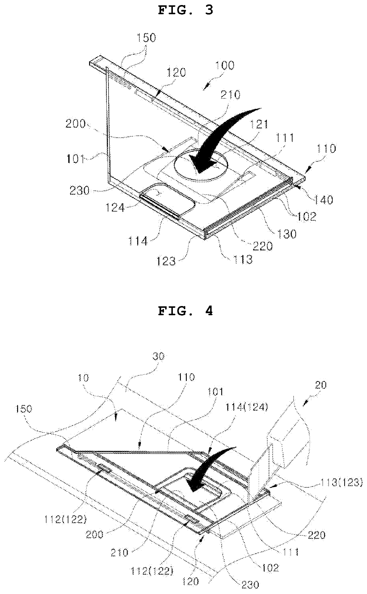
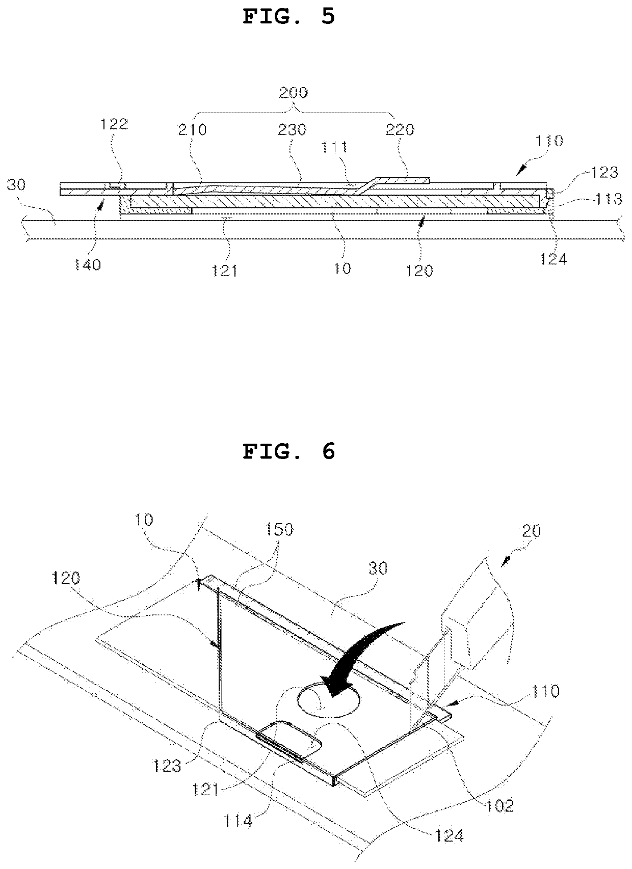
The present invention provides a panel cutting jig that can securely and evenly cut a plate-shaped panel. This helps to avoid uneven surfaces and improves the overall quality of the finished product.

Problems solved by technology

As a result, as the wood panel is unstably fixed and cut, the cutting surface of the wood panel may be uneven.

Method used


Image

  • Panel cutting jig
  • Panel cutting jig
  • Panel cutting jig

Examples


Embodiment Construction

[0026]The advantages and features of the present disclosure and methods of achieving them will be apparent from the embodiments that will be described in detail with reference to the accompanying drawings. It should be noted, however, that the present disclosure is not limited to the following embodiments, and may be implemented in various different forms. Rather the embodiments are provided so that this disclosure will be thorough and complete and will fully convey the scope of the present disclosure to those skilled in the technical field to which the present disclosure pertains, and the present disclosure will only be defined by the appended claims.

[0027]Terms used in the specification are used to describe embodiments of the present disclosure and are not intended to limit the scope of the present disclosure. In the specification, the terms of a singular form may include plural forms unless otherwise specified. The expressions “comprise” and / or “comprising” used herein indicate t...


PUM


Abstract

The present disclosure relates to a panel cutting jig including: a main body having an insertion channel, into which a plate-shaped panel is inserted, formed therein; and a holder that is elastically deformable and supports the main body to generate elastic force toward the insertion channel.

Description

CROSS-REFERENCE TO RELATED APPLICATION[0001]A claim for priority under 35 U.S.C. § 119 is made to Korean Patent Application No. 10-2021-0009327 filed on Jan. 22, 2021 in the Korean Intellectual Property Office, the entire contents of which are hereby incorporated by reference.BACKGROUND1. Technical Field[0002]The present disclosure relates to a panel cutting jig capable of stably fixing and cutting a plate-shaped panel.2. Description of Related Art[0003]In general, among the panel-like panels, wood panels include plywood, Medium Density Fiber (MDF) panels, Low Pressure Melamine (LPM) panels (Panel), as well as Particle Board (PB) panels, and are widely used as various building materials and furniture materials.[0004]These wood panels have high strength as well as good workability, and are suitable for bonding patterned sheets, so they have been widely used in recent years.[0005]The wood panel is cut to a specific size to be suitably sized for use in various construction sites or ind...

Claims


Application Information

Patent Timeline
Patent Type & Authority Applications(United States)
IPC IPC(8): B25B11/02
CPCB25B11/02B27B29/02B27C9/00B27C5/04
Inventor KIM, SANG GONLEE, JONG WOO
Owner RICO BLINDS CO LTD
Learn More