Centrifugal multi-blade blower

a centrifugal multi-blade blower and multi-blade technology, which is applied in the direction of machines/engines, stators, liquid fuel engines, etc., can solve the problems of impeller loss, air flow exfoliation in the inter-vane,

Inactive Publication Date: 2015-07-09
DENSO CORP
View PDF5 Cites 13 Cited by
  • Summary
  • Abstract
  • Description
  • Claims
  • Application Information

AI Technical Summary

Benefits of technology

[0019]The present disclosure addresses the above issues. Thus, it is an objective of the present disclosure to provide a centrifugal multi-blade blower that can sufficiently evenly make a flow speed distribution in a rotation axis direction on an air outlet side of an impeller.
[0020]To achieve the above-described objective, the present inventors have earnestly given a great deal of consideration. As a result, with their attention turned to the fact that in a centrifugal multi-blade blower, a flow rate of an impeller on its air outlet side increases in proportion to the second power of an outer peripheral diameter of the impeller under conditions where rotating speed and draft resistance are constant, they have worked out a centrifugal multi-blade blower that can evenly make a flow speed distribution on the air outlet side of the impeller.
[0022]As described above, in such a configuration that the inlet angle is evenly made in the entire region from the side plate side through the main plate side, the outer peripheral diameter of the impeller is larger on the side plate side than on the main plate side. Accordingly, a flow rate on the air outlet side on the side plate side of the impeller can be increased. As a consequence, a flow speed on the air outlet side on the side plate side of the impeller can be increased compared to the impeller of the conventional technology.
[0023]Moreover, in accordance with the increase of the flow rate on the air outlet side on the side plate side of the impeller, a flow rate of air flowing into the inner peripheral edge part on the side plate side increases. This increase of the flow rate of air flowing into the inner peripheral edge part on the side plate side makes faster a flow speed (absolute inflow speed) on the side plate side. Accordingly, an inflow angle on the side plate side can be brought close to the inlet angle.
[0024]As a result, the exfoliation of the air flow on the side plate side can be restricted as compared with the impeller of the conventional technology, and there can be mitigated a reduction of the flow speed on the air outlet side on the side plate side in association with the exfoliation of the air flow on the side plate side.
[0025]For the above reason, the centrifugal multi-blade blower of the present disclosure can sufficiently evenly make a flow speed distribution in the rotation axis direction on an air outlet side of the impeller, which becomes an issue in the impeller of the conventional technology.

Problems solved by technology

In a case of a large difference (incidence angle) between an inlet angle (inlet condition) of an inner peripheral edge of the vane and an inflow angle (inflow condition) of the air flowing into the vane, there is a tendency that the air flow exfoliates in the inter-vane space, and the impeller of the centrifugal multi-blade blower loses speed.

Method used


Image

  • Centrifugal multi-blade blower
  • Centrifugal multi-blade blower
  • Centrifugal multi-blade blower

Examples


first embodiment

[0052]A first embodiment will be described below. In the present embodiment, a centrifugal multi-blade blower of the present disclosure is applied to an air-conditioning system 1 for a vehicle including a water-cooled engine.

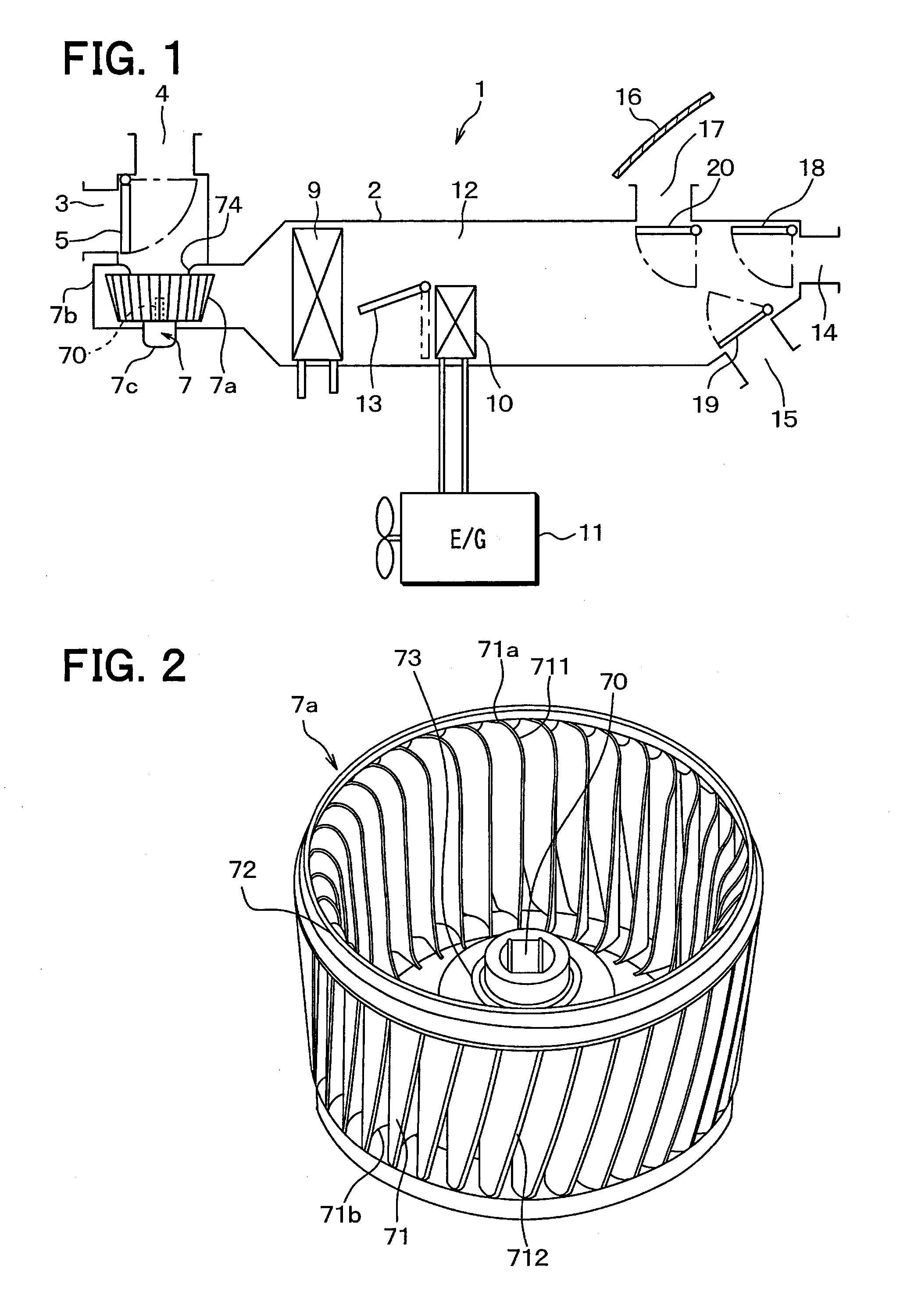
[0053]As illustrated in FIG. 1, the air-conditioning system 1 includes an air-conditioning casing 2 that defines an air passage for blown air which is blown into a vehicle interior. At an uppermost stream side part of the air-conditioning casing 2 in an air flow direction, there are formed an inside air introduction port 3 for introducing inside air (vehicle interior air), and an outside air introduction port 4 for introducing outside air (vehicle exterior air), and there is provided an inside-outside air switch door 5 for selectively opening or closing these introduction ports 3, 4.

[0054]A blower 7 is disposed on a downstream side of the inside-outside air switch door 5 in an air flow direction, and the air introduced through the introduction ports 3, 4 is blow...

second embodiment

[0097]A second embodiment will be described below. In the present embodiment, an example of modification of the shape of the main plate 73 to the first embodiment will be described. In the present embodiment, explanation will be given with the description of a part similar or equivalent to the first embodiment omitted or simplified.

[0098]In an impeller 7a of the present embodiment, an outer peripheral diameter of a main plate 73 is made smaller than in the first embodiment as illustrated in a perspective view in FIG. 11, a half sectional view in FIG. 12, and a top view in FIG. 13. Specifically, in the present embodiment, as illustrated in FIG. 13, the outer peripheral diameter of the main plate 73 is made small such that the main plate 73 and a forward part 711a of an inner peripheral edge part 711 do not overlap with each other when the impeller 7a is viewed from the rotation axis direction.

[0099]More specifically, as illustrated in a meridian plane diagram in FIG. 14, a distance L...

third embodiment

[0103]A third embodiment will be described below. In the present embodiment, an example of modification of the shape of the impeller 7a to the first and second embodiments will be described. In the present embodiment, explanation will be given with the description of a part similar or equivalent to the first and second embodiments omitted or simplified.

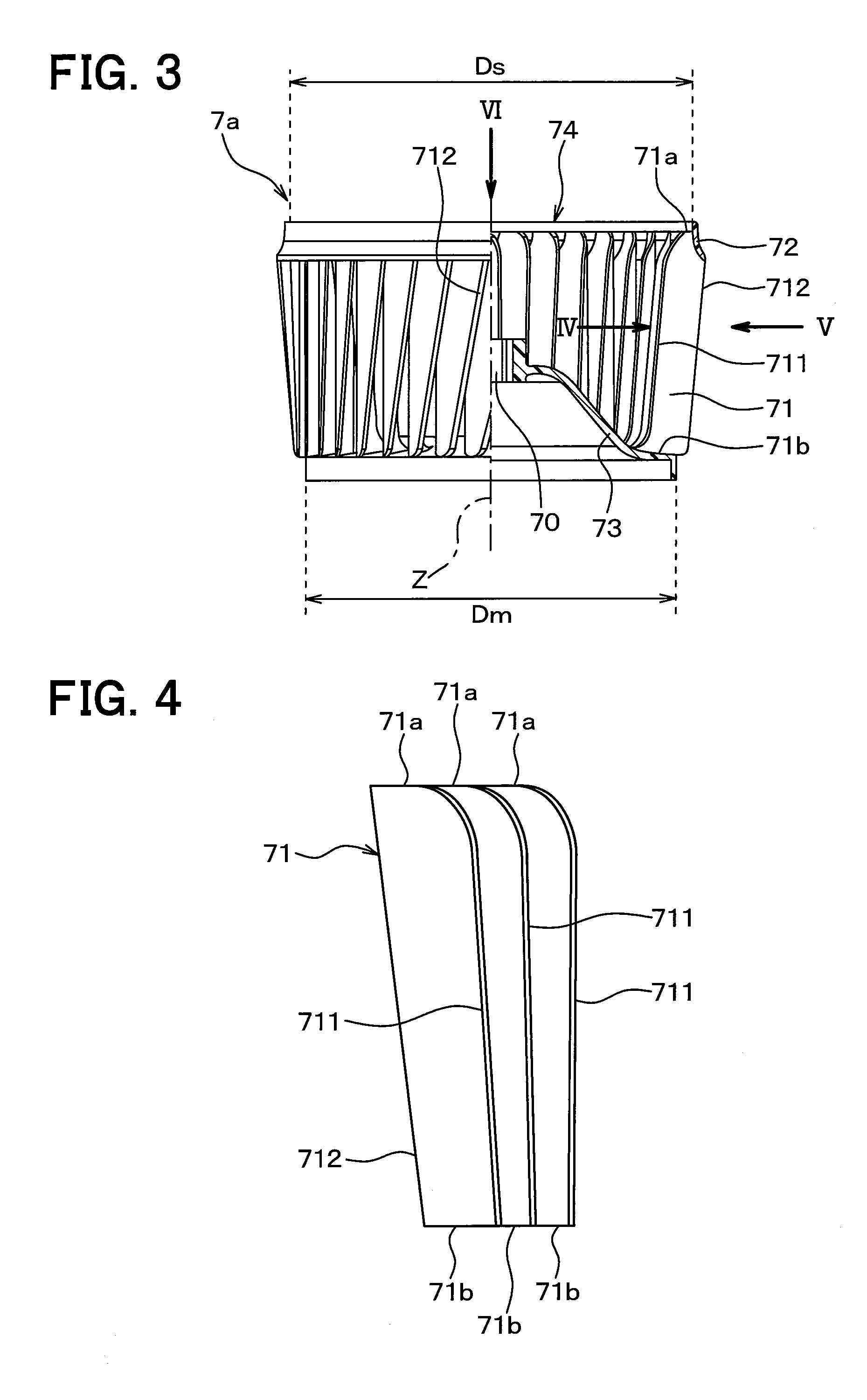
[0104]In the present embodiment, as illustrated in FIG. 15, a ratio of an outer peripheral diameter D1 to an inner peripheral diameter d1 of an impeller 7a on a side plate 72-side (side-plate side inner-outer diameter ratio) is larger than a ratio of an outer peripheral diameter D2 to an inner peripheral diameter d2 of the impeller 7a on a main plate 73-side (main-plate side inner-outer diameter ratio) (D1 / d1>D2 / d2).

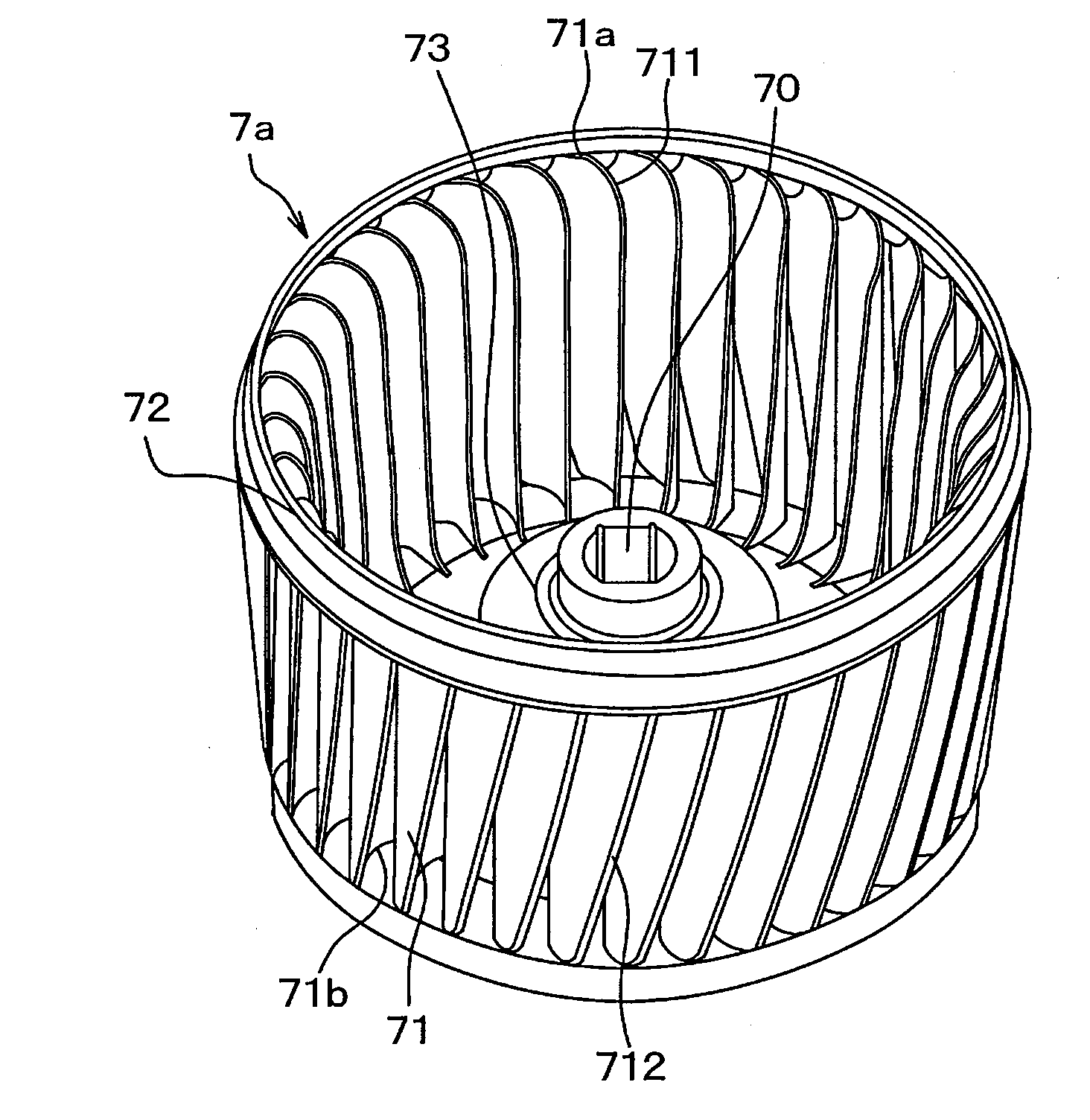
[0105]Specifically, in the present embodiment, outer peripheral edge parts 712 of vanes 71 are configured to be away from an axis Z of a rotation shaft 70 from the main plate 73-side toward the side plate 72-side, and inne...


PUM


Abstract

A centrifugal multi-blade blower includes an impeller, and a casing that accommodates the impeller, and draws in air at least from an inlet port of the casing which opens on one end side of a rotation shaft and blows out the air radially outward of the rotation shaft. The impeller includes a main plate that is joined to the rotation shaft, vanes which are arranged around the axis of the rotation shaft and the other end sides of which in the rotation axis direction are connected to the main plate, and a side plate that connects together the vanes on their one end sides in the rotation axis direction. The vanes are characterized in that an inlet angle on a cross-sectional surface crossing each inner peripheral edge part of the vanes on a meridian plane of the impeller in a predetermined direction is evenly made in the entire region from the side plate-side through the main plate-side, and that outer peripheral edge parts of the vanes are configured to be away from the axis of the rotation shaft from the main plate-side toward the side plate-side.

Description

CROSS REFERENCE TO RELATED APPLICATION[0001]This application is based on Japanese Patent Application No. 2012-142803 filed on Jun. 26, 2012 and Japanese Patent Application No. 2013-100170 filed on May 10, 2013, the disclosures of which are incorporated herein by reference.TECHNICAL FIELD[0002]The present disclosure relates to a centrifugal multi-blade blower that draws air from a direction of a rotation axis and blows out the air radially outward of the rotation axis.BACKGROUND ART[0003]An impeller of a conventional centrifugal multi-blade blower includes vanes arranged around the rotation axis, and blows out radially outward the air, which is drawn from the direction of the rotation axis.[0004]In this impeller, a wind direction rapidly changes from the rotation axis direction to the radial direction at spaces between adjacent vanes (hereinafter referred to as an inter-vane space) near an air inlet. Accordingly, the air does not flow easily compared to on an opposite side from the i...

Claims


Application Information

Patent Timeline
Patent Type & Authority Applications(United States)
IPC IPC(8): F04D29/28F04D29/30F04D17/10
CPCF04D29/281F04D29/30F04D17/10F04D17/162F04D29/282F04D29/283
Inventor SAKAI, MASAHARUIMAHIGASHI, SHOUICHI
Owner DENSO CORP
Why Eureka
Try Eureka